ASSEMBLY INSTRUCTIONS
TALL CABINET - MODEL CS30
To avoid SERIOUS INJURY or DAMAGE to personal belongings:
• DO NOT overload the cabinet or the shelves, maximum weight
limit for feet or caster installation is 75 lbs. for each shelf, and
50 lbs. for the wardrobe bar. Maximum weight limit for wall
mounting is 45 lbs. for each shelf and 50 lbs. for the wardrobe
bar.
• DO NOT climb, step, or hang on the cabinet.
• Tether and secure finished cabinet to wall stud using the
included hardware when feet or casters are used.
• If hanging the cabinet, follow instructions for wall mounting.
A
C
G
F
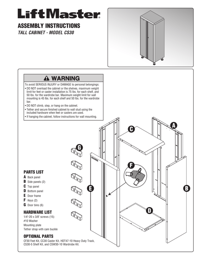
PARTS LIST
A
B
C
D
E
F
G
Back panel
Side panels (2)
Top panel
Bottom panel
E
B
Door frame
Keys (2)
Door bins (6)
HARDWARE LIST
1/4"-20 x 3/8" screws (15)
#10 Washer
Mounting plate
Tether strap with cam buckle
OPTIONAL PARTS
CF30 Feet Kit, CC30 Caster Kit, HDT47-10 Heavy Duty Track,
CS30-5 Shelf Kit, and CSW30-10 Wardrobe Kit.
D
TOOLS NEEDED
•
•
•
•
Drill
7/32" Drill Bit
5/16" and 7/16" Sockets
7/16" Open-end wrench
•
•
•
•
#2 Phillips Bit
Flashlight
Rubber mallet
Tape Measure
•
•
Stud Finder
Nutdriver Power Bit Magnetic
1/4" Hex Shank, 5/16" hex size,
7/16" hex size
•
•
•
Level
Pencil or Marker
Hydraulic Lift or Mover Straps
ASSEMBLY 1
IMPORTANT NOTE: For a successful assembly, ensure that all pieces are
aligned correctly BEFORE securing with screws.
1. Lay the back panel (A) on the floor.
2. Align both side panels (B) with the back panel (the side panels
will fit behind the back panel). Connect by inserting the tabs into
the cutouts.
B
A
B
Tab
Cutout
Insert tabs into cutouts
ASSEMBLY 2
1. Align the top panel (C) with the back (A) and side panels (B) and
insert the tabs into the cutouts.
2. Ensure that the front edges are aligned and flush. Tap the pieces into
place with a rubber mallet if necessary.
3. Secure the top panel (C) with 1/4"-20 screws (6) (torque
spec: 30-40 in/lbs.).
C
C
B
1/4"-20
screws
A
B
2
Front edges
aligned and flush
ASSEMBLY 3
1. Align the bottom panel (D) with the back (A) and side panels
(B) and insert the tabs into the cutouts.
2. Ensure that the front edges are aligned and flush. Tap the
pieces into place with a rubber mallet if necessary.
3. Secure the bottom panel (D) with 1/4"-20 screws (6) (torque
spec: 30-40 in/lbs.).
1/4"-20
screws
B
A
B
D
D
Front edges
aligned and flush
ASSEMBLY 4
1. Remove the keys from the door assembly (E), leave the
doors locked.
2. Align the door frame to the cabinet (LiftMaster® logo is on
the top of the left door).
3. Slide door assembly down to insert the tabs into the cutouts.
4. Unlock and open doors. Verify that the edges are level.
5. Secure with 1/4"-20 screws (2) (torque spec: 30-40 in/lbs.).
6. Lock doors.
E
1/4"-20
screws
Edges level
3
ASSEMBLY 5
Instructions will vary according to the optional equipment purchased. Follow the instructions for your application. NOTE: If using the CSW30-10
Wardrobe Kit, install the weights as shown. DO NOT install the weights if the cabinet is to be wall mounted.
CF30 FEET KIT
CC30 CASTER KIT
1. Position the legs on the bottom panel (D). The tab on the leg must fit
into the cutout on the bottom panel.
2. Secure each leg with the bolts provided (torque spec: 80-90 in/lbs.).
3. Adjust the height of the legs as needed (a notch in the leg indicates
maximum height). The leg will adjust from 4-6" in height. Turn the
leg counter-clockwise to make it longer and clockwise to make it
shorter. NOTE: One full turn changes the height 3/32".
4. Raise the cabinet into an upright position (may require two people).
1. Position the casters on the bottom panel (D) with the brakes toward
the front of the cabinet. The tab on the caster must fit into the cutout
on the bottom panel.
2. Secure each caster with the bolts provided.
3. Raise the cabinet into an upright position (may require two people).
NOTE: CC30 Caster Kit installation instructions apply to the CB30 Base
Cabinet and the CT30 Tool Cabinet.
Tab
Notch
(maximum height)
Cutout
Weights (applicable for
the CSW30-10
Wardrobe Kit ONLY)
Cutout
Brake
Cutout
Tabs
Cutout
D
4
D
Weights (applicable for
the CSW30-10
Wardrobe Kit ONLY)
INSTALLATION
For additional stability use the tether to secure the cabinet to the wall:
1. Level the cabinet to the desired height.
2. Measure the distance from the floor to middle of vertical slots in the
back of the cabinet along the top edge.
3. Find the closest stud to the center of the cabinet and locate the
centerline of the stud at the measured height of vertical slots
4. Along the center line of the stud mark with a pencil 1-1/8" above the
measured height. This is the location to place the top mounting
screw for the mounting plate.
5. Drill a 7/32" pilot hole at the marked location. Attach the mounting
plate to the wall using a 5/16"x2-1/2" lag screw HDF02.
6. In the center of bottom hole drill a 7/32" pilot hole and attach another
5/16" lag screw HDF02.
7. The tether strap will be looped, starting from inside the cabinet
through the slots in the back of the cabinet, through the mounting
plate on the wall, and back into the cabinet through a second slot
where it will be secured with the buckle.
With the cabinet a couple of feet away from the wall, determine the
closest slot in the cabinet to the mounting plate. Note which slot this
is (count from corner or mark) and locate it from inside the cabinet.
Slide free end of the tether through one slot left (looking from inside
the cabinet) of the identified slot so it sticks out the back of the
cabinet. Go back to outside the cabinet and feed the free end of the
tether through the mounting plate on the wall. Return the free end of
the tether back into the cabinet through one slot right (looking from
inside the cabinet) of the identified center slot. NOTE: There should
be one empty slot between the two slots used to route the tether
strap into the cabinet.
8. Push the cabinet against the wall. Run the free end of tether strap
though cam buckle from the underside of the buckle. Metal cam
buckle teeth are designed so that webbing can be pulled up and
through the mouth of the buckle to tighten. The teeth will grip the
webbing and not let it slip back down. Pull strap tight so no slack
remains in the system. NOTE: To get buckle over the top inside lip of
the cabinet it may have to be angled slightly.
9. Loop the extra strap and tie together and place in top lip.
Lag Screw
5/16"x2-1/2"
Mounting
plate
Tether
Buckle
Pre-drill holes for
mounting plate
Top inside lip
(back of cabinet)
Mid point of the slots
on back of cabinet
Slot on cabinet
Height for the
middle of the
mounting plate
5
OPTIONAL HDT47-10 HEAVY DUTY
TRACK FOR WALL MOUNTING
1. Determine the top of the cabinet height.
2. The heavy duty wall track must attach to three wall studs spaced on
16" centers. Do not mount to wall if studs are spaced on 24" centers.
Locate three wall studs in the desired position of the cabinet. From
one end of the cabinet pick the closer stud. This stud is where the
first pre-drilled mounting hole in the heavy duty wall track should
mount.
3. Measure down from the ceiling to the desired top of cabinet height.
Increase this dimension by one inch for the location of the top of the
heavy duty wall track and mark the center line of the three studs at
this location. It is important to install the lag screws as close to the
middle of the stud as possible.
4. Align the top of the heavy duty wall track with the stud marks. Before
installing the 5/16" lag screws in the large holes in middle of track, it
is imperative to drill 7/32" pilot holes into the studs.
5. Attach track with first lag screw to wall.
6. Level the heavy duty wall track with a level and secure to the wall
with the remaining lag screws.
NOTE: If more than one cabinet is to be hung, a second heavy duty
wall track will be required. Locate the three studs to be used. Align
top of second heavy duty wall track with one installed. Leave a 1" gap
between the tracks so that the pre-drilled holes in the second track
will align with the studs. Repeat previous procedure.
7. Measure from top of heavy duty wall track down 54.5" and at the
center of each stud mark approximately a 2" long vertical line (1"
above and 1" below the 54.5" mark). Make the line as dark as
possible.
8. Hang the track on the back of the cabinet onto the heavy duty wall
track using the hydraulic lift or mover straps. In the correct position
the tracks “hook” onto each other.
To avoid SERIOUS INJURY or DAMAGE to personal belongings:
• DO NOT overload the cabinet or the shelves. Maximum weight limit
for wall mounting is 45 lbs. for each shelf and 50 lbs. for the
wardrobe bar.
• DO NOT climb, step, or hang on the cabinet.
9. The cabinet must be secured to a wall stud towards the bottom of the
cabinet so it cannot pivot away from the wall and/or lift up or move
on the heavy duty wall track.
• Open the doors to the cabinet. At the bottom the cabinet will be
horizontal slots.
• Using the flashlight look through the slots and find one of the
vertical lines placed on the wall previously. These vertical lines
represent where a #10 deck screw (HDF03) can be screwed into a
stud to hold the cabinet firm to the wall.
• Before screwing into the wall, slide a flat washer (provided with
cabinet) onto the deck screw.
• Screw the deck screw into the stud until the flat washer hits the
back of the cabinet. Only one screw is required.
1" gap between 2 heavy duty wall tracks
Track
HDF02 Steel 5/16" hex
washer head lag screw
Line for
stud location
Wall
Track
SIDE VIEW
#10 Deck Screw and Washer
fastened to stud through slot
Slot on inside
of cabinet
INSIDE OF CABINET
6
SETUP STORAGE SPACE
Attach the door bins, shelves and wardrobe
bar by inserting the tabs into the brackets
in the cabinet.
CS30-5 SHELF KIT
(OPTIONAL)
Brackets
Tabs
DOOR BINS
6 bins included
with the cabinet.
Tabs
Tabs
CSW30-10 WARDROBE KIT
(OPTIONAL)
Includes a set of 2 weights
(Previously installed - see
Assembly Step 5)
REPLACEMENT PARTS
•
•
SHDK Spare Hardware kit:
1/4"-20 x 3/8" Screws (34)
1/4"-20 x 2" Drawer Assembly Screws (6)
5/16"-18 X 1" Jumbo Assembly Screws (16)
SKKE Keys (2)
7
DISCLAIMER
The Chamberlain, Group, Inc. and its affiliated corporations and
subsidiaries (“Chamberlain”) intend to make these instructions accurate
and complete; however, Chamberlain makes no claim that the
information contained herein covers all conditions, variables and
contingencies in connection with the installation or use of this product.
Chamberlain assumes no liability for any personal injury or property
damage that results from the installation or use of this cabinet. For any
cabinet attached to a structural wall, State, Regional and/or local building
codes related to loading may be impacted. It is the responsibility of the
purchaser to insure that those codes or regulations are complied with.
Chamberlain makes no representation, warranty or guarantee in that
regard. Purchasers of Chamberlain makes no representation of warranty,
expressed or implied, regarding the information contained herein.
Chamberlain assumes no responsibility for the accuracy, completeness
or sufficiency of the information contained herein.
FOR TECHNICAL SUPPORT DIAL OUR TOLL FREE NUMBER:
1-800-528-3536
114A4517C
© 2012, The Chamberlain Group, Inc.
All Rights Reserved


