File - GIAP Journals
advertisement

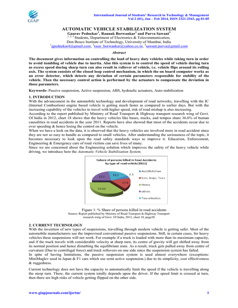
International Journal of Students’ Research in Technology & Management Vol 2 (01), Jan – Feb 2014, ISSN 2321-2543, pg 01-05 AUTOMATIC VEHICLE STABILIZATION SYSTEM Gaurav Pednekar1, Raunak Borwankar2 and Purva Sawant3 Students, Department of Electronics & Telecommunication, Don Bosco Institute of Technology, University of Mumbai, India 1 gpednekar4@gmail.com, 2raun_borwankar@yahoo.co.in, 3sawant.purva@gmail.com 1, 2, 3 Abstract The document gives information on controlling the load of heavy duty vehicles while taking turn in order to avoid tumbling of vehicle due to inertia. Also this system is to control the speed of vehicle during turn as excess speed during sharp turn can also result in rollover of vehicle, i.e. vehicle flips around its rolling axis. The system consists of the closed loop control mechanism, in which the on board computer works as an error detector, which detects any deviation of certain parameters responsible for stability of the vehicle. Then the necessary control action is performed by the actuators to compensate the deviation in those parameters. Keywords- Passive suspension, Active suspension, ABS, hydraulic actuators, Auto-stabilization 1. INTRODUCTION With the advancement in the automobile technology and development of road networks, travelling with the IC (Internal Combustion) engine based vehicle is getting much faster as compared to earlier days. But with the increasing capability of the vehicles to travel with higher speed, risk of road mishap is also increasing. According to the report published by Ministry of Road Transport & Highway transport research wing of Govt. Of India in 2012, chart 18 shows that the heavy vehicles like buses, trucks, and tempos share 36.6% of human causalities in road accidents in the year 2011. Reports have also showed that most of the accidents occur due to over speeding & hence losing the control on the vehicle. When we have a look on the data, it is observed that the heavy vehicles are involved more in road accident since they are not so easy to handle as compared to small vehicles. After understanding the seriousness of the topic, it becomes necessary to look upon the road safety standards ways to improve it. Education, Enforcement, Engineering & Emergency care of road victims can save lives of many. Since we are concerned about the Engineering solution which improves the safety of the heavy vehicle while driving, we introduce here the Automatic Vehicle Stabilization System. Figure 1: % Share of persons killed in road accidents Source: Report published by Ministry of Road Transport & Highway Transport research wing of Govt. Of India, 2012, chart 18, page20 2. CURRENT TECHNOLOGY With the invention of new types of suspensions, travelling through modern vehicle is getting safer. Most of the automobile manufacturers use the improvised conventional passive suspensions. Still, in certain cases, for heavy vehicles these suspensions will not work. For example if a truck is loaded with more than its maximum capacity, and if the truck travels with considerable velocity at sharp turn, its centre of gravity will get shifted away from its normal position and hence disturbing the equilibrium state. As a result, truck gets pulled away from centre of curvature (Due to centrifugal force) and truck rollovers on one side since the suspension system has failed. In spite of having limitations, the passive suspension system is used almost everywhere (exceptions: MiniMaglev used in Japan & F1 cars which use semi active suspension.) due to its simplicity, cost effectiveness & ruggedness. Current technology does not have the capacity to automatically limit the speed if the vehicle is travelling along the steep turn. There, the current system totally depends upon the driver. If the speed limit is crossed at turn, then there are high risks of vehicle getting flipped on the other side. www.giapjournals.com/ijsrtm/ 1 International Journal of Students’ Research in Technology & Management Vol 2 (01), Jan – Feb 2014, ISSN 2321-2543, pg 01-05 3. REPLACEMENT NEEDED IN CURRENT TECHNOLOGY The current technology is reliable and tested against harsh circumstances. Still it requires improvement so that technology can back up the driver. With the development in the microelectronics, a small computer on board can be installed in the vehicle to monitor all parameters which play a vital role to maintain the stability & handling of the vehicle. When certain parameter is exceeding the limit, actuators can be driven to compensate that error. Simultaneously, an alarming system can be incorporated within it. 4. WHAT IS AUTOMATIC VEHICLE STABILIZATION SYSTEM The system for heavy-duty vehicle will have 3 main blocks: a. Sensors b. Microcontroller c. Active suspension & Actuators Figure 2: Block diagram of the Automatic Vehicle Stabilizing System (AVSS) a. Sensors: The sensors used in this system are basically active transducers which work on tachometric principle i.e. these sensors are mounted near shaft of wheels of vehicle. These sensors generate the train of pulses, which has frequency proportional to the speed of vehicle. These tachometric transducers are available in various types such as Hall-effect tachometers, & opto–isolated tachometers. Considering the ruggedness, Hall Effect sensor is more popular. The above block diagram is of Hall Effect sensor or tachometer. It has one significant component, called as the Hall probe, and mounted near the wheel of the vehicle, very close to the toothed structure on the shaft. This probe has solenoid made up of Copper with the magnetic material rod at the centre of the probe. When supply voltage is applied to the probe, the current starts flowing in the solenoid, developing the magnetic field around it. The probe carries the magnetic flux & radiates it in the small air gap between the probe & the toothed gear. Due to the toothed structure & its rotation, probe develops the train of pulses at its output. The electrical signal developed by the transducer is in the form of the pulses. But, it may contain some irregularities. So, some signal shaping circuits are required. For this purpose, active Schmitt Trigger can be used. Now, this clean train pulse is applied to the input of the counter circuit, which will count these pulses and give the digital output word. The electrical signal developed by the transducer is in the form of the pulses. But, it may contain some irregularities. So, some signal shaping circuits are required. For this purpose, active Schmitt Trigger can be used. Now, this clean train pulse is applied to the input of the counter circuit, which will count these pulses and give the digital output word. Figure 3: Block schematic of Hall-effect tachometer Figure 4: The Hall probe b. Microcontroller (On Board Computer) The microcontroller AT89C51 is programmed in such way that it monitors on the parameters like velocity of the vehicle, degree by which vehicle is turning. According to the data, it will take actions to move actuators in such a way that vehicle is stabilized properly. The controller will also monitor & the speed of vehicle, & control it by www.giapjournals.com/ijsrtm/ 2 International Journal of Students’ Research in Technology & Management Vol 2 (01), Jan – Feb 2014, ISSN 2321-2543, pg 01-05 actuators. Considers the digital equivalent value of the parameters like speed & rate of change of angle of front wheel shaft. If the vehicle is taking the turn, then according to mathematical formula in program, the controller calculates the amount of force to be delivered to the load which is the function of speed & derivative of angular displacement with respect to time. The output received from microcontroller will be just 0 or 1 at any of its port pins according to availability & requirement. The 8051 family has 8 bit ALU, four 8-bit addressable ports, on chip timer, counter with control word, and interrupt registers. The data from the signal processing circuits is allowed to enter into the controller. Controller will have program stored in its EEPROM. But, microcontroller gives out current in the range of 50 to 650 µA, which is not sufficient to drive the actuators. So, we use current amplifiers to drive actuators which are high power devices like motors in actuators & active suspensions. Figure 5: The AT89C51 Microcontroller c. Active suspension & Actuatorsi. Active suspension (To manipulate load position) Active suspensions are electronically controlled suspensions which have capability to vary their stiffness & damping even if physical dimensions are not changed. Figure 6: Active suspension systems used for car On the basis of working principle of operating principle, types of suspension may vary. Such as the heavy vehicle will need hydraulic suspension, while medium scale can be handled with pneumatic suspension. For heavy duty vehicle, we consider hydraulic suspensions & actuators. In hydraulics, we use uncompressible & viscous fluid such as oil, to move piston in or out of the cylinder. So this fluid is pressurised by using electric pump or motor in the actuator. The motor will start or stop applying pressure according to signal received by microcontroller. Now, these actuators will regulate their piston movement in such a way that it stabilizes the vehicle. Figure 7: The mathematical model and transfer function of Active suspension www.giapjournals.com/ijsrtm/ 3 International Journal of Students’ Research in Technology & Management Vol 2 (01), Jan – Feb 2014, ISSN 2321-2543, pg 01-05 Figure 8: Root locus for the active suspension system using above transfer function. Figure 9: Response of Active suspension system to step input ii. Actuators (For active breaking) Similar to the active suspension, active breaking uses the same operating principle, i.e. the hydraulics. It consists of components like master cylinder, piston, valves, & a pump (motor). When vehicle is about to take turn, the sensor from steering wheel gives triggering input to the system, by which microcontroller in the system monitors the values of various parameters such as cornering angle, lateral force on the load etc. & if any value exceeds than its limit, then gradual breaking of wheels is applied. Simultaneously, the electronically operated fuel injector valve trips engine from fuel supply. Thus, even if operator hits accelerator, engine will not be able to generate any increase in output. The vehicle hence slows down and becomes steadier. Still if the system is not able to stabilize the load & chassis of the vehicle, the high power suspension system applies reaction force against the weight of the vehicle. A similar system is existing in the form of ABS i.e. Anti-locking breaking system, but it does manipulate the load of vehicle. 5. APPLICATIONS The system can be used for safe transport of goods & people with more safety than earlier. www.giapjournals.com/ijsrtm/ 4 International Journal of Students’ Research in Technology & Management Vol 2 (01), Jan – Feb 2014, ISSN 2321-2543, pg 01-05 In country like India, where road safety standards are not strictly followed, successful design of this system can be used to test reliability & safety of existing vehicles. The same system is applicable for high speed railways with some changes in configuration. 6. CONCLUSION: The paper presents the concept of closed loop control system used to maintain stability of heavy vehicle. The AVSS can improve the handling of heavy vehicles even better. More importantly, it is a solution over the problem of rollover of heavy vehicles which takes almost thousands of precious lives over the globe. REFERENCES 1. http://www.designboom.com/technology/worlds-first-fully-regenerative-active-suspension-system/ 2. http://en.wikipedia.org/wiki/Anti-lock_braking_system 3. Principles of Control Systems by M. Gopal 4. http://www.engineershandbook.net/suspension-system-with-matlab-simulink/ 5. http://www.frpatentsonline.com/6338012.html 6. http://en.wikipedia.org/wiki/Rollover www.giapjournals.com/ijsrtm/ 5


