Product Verification Testing
108-106099
June 29th, 2012 Rev. A
SOLARLOK PV4 Connector
1. Reference Documents
EN 50521: Connectors for photovoltaic systems - Safety requirements and tests
EN 60512-12: Connectors for electronic equipment -- Test and measurements
EN 60529: Degrees of Protection Provided by Enclosures (IP Code)
EN 60664-1: Insulation coordination for equipment within low-voltage systems (Part 1)
EN 60695: Fire hazard testing (Part 2-10, Part 11-10,)
Safety class II
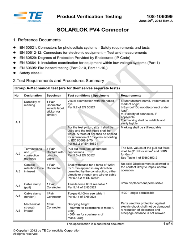
2.Test Requirements and Procedures Summary
Group A-Mechanical test (are for themselves separate tests)
No.
Designation
Specimen
Test conditions / Specimens
Requirements
Durability of
marking
1 Pair
Connector
include label,
sticker (or
similar)
Visual examination with the naked
eye
Per 5.2 of EN 50521
a) Manufacture name, trademark or
mark of origin;
l) Symbol “Do not disconnect under
load”;
m) Polarity of connector, if
applicable
The marking shall be indelible and
easily legible.
Marking shall be still readable
A.1
For the test piston, size 1 shall be
used and the test liquid shall be
water. A force of 5N shall be applied
for a duration of 10 cycles according
to IEC 60068-2-70
Per 6.3.2 of EN 50521
Pull out force test of crimped
connections
Per 5.5 of EN 50521
The Min. values of the pull out force
2
shall be 310N for 4mm and 360N
2
for 6mm
See Table 1 of EN60352-2
Contact
1 Pair
retention force Connector
in insert
Shall withstand for a force of 125N
for 1 min applied in any direction
permitted by the construction, either
directly or through any wire or cable
Per 5.15.2 of EN 50521
No axial Displacement is allowed to
the contact likely to impair normal
operation
Cable clamp
(pull)
1 Pair
Connector
Tensile force 60N see table 1
Per 5.14 of EN50521
3mm displacement permissible
A.4
Cable clamp
(torsion)
1Pair
Connector
Torque 0.10Nm see table 1
Per 5.14 of EN50521
±30°angle permissible
A.5
1Pair
Connector
A.6
Mechanical
strength
impact
Dropping height:
- 750mm for specimens of mass≤
250g
- 500mm for specimens of
mass>250g
Parts used for protection against
electric shock shall not be damaged.
A reduction of clearance and
creepage distance is not allowed.
A.2
A.3
Terminations
and
connection
methods
1 Pair
Contact with
crimping
cable
This specification is a controlled document
© Copyright 2012 by TE Connectivity Corporation
All rights reserved
1 of 4
Product Verification Testing
108-106099
June 29th, 2012 Rev. A
Dropping cycles:8
positions in 45°step, one cycles per
position
A.7
A.8
Mechanical
strength at
lower
temperature
1 Pair mated
connector
Insertion force
(Mating force)
1 Pair
connector
Four impact on the specimen, an
energy of 1 joule after being cooled
and maintained for 5h at a
temperature of minus 40.0℃ on a
steel plate of 20mm thickness
Per 6.3.10 of EN 50521
No damage likely to impair the
function of the connector
Per 5.15 of EN50521
The specified force shall be applied in
the direction of the insertion of the
unmated pair with the rate of
50mm/min.
The Max. values of insertion force
shall be 70N
Per 5.16 of EN50521
Per 6.3.13 of EN 50521
Withdrawal
force
(Un-mating
force)
A.9
Effectiveness
of connector
coupling
device
A.10
(Separation
force)
1 Pair
Only for
mated
connector
disengaged
locking
device or
snap-in
device
The specified force shall be applied in
the direction of the separation of the
mated pair with the rate of 50mm/min
1 Pair
Only for
mated
connector
with locking
device or
snap-in
device.
The specified force shall be applied in
the direction of the separation of the
mated pair with the rate of 10 N/sec.
The Max. values of withdrawal force
shall be 70N
Per 5.16 of EN50521
Per 6.3.13 of EN 50521
Per 6.3.14 of EN50521
Connector with locking device or
with snap-in device shall withstand a
load of 80N at least
Per 5.17 of EN 50521
Note Test group A consists of separate tests. There is no required test sequence.
Group B- Service life Test
No.
B.1
B.2
Designation
Specimen
Test conditions / Specimens
Requirements
Contact
Resistance
(initial)
3 Pair Mated
Connector
Test current:1A
a
Measure points at the end of the
termination
The Max. values shall be 0.5mΩ
Following B1
Shall be engaged and disengaged by
means of
A) a device simulating normal
operating conditions, the speed of
insertion and withdrawal shall be
approximately 0.01m/s with a rest in
the unmated position of
approximately 30s
B) manual mating/un-mating 300
Max. cycle per hour
Per 6.3.5 of EN 50521
1) 100 operation cycles without load
2) No damage likely to impair
function
Per 5.11.1 of EN 50521
Mechanical
Operation
(Durability)
This specification is a controlled document
© Copyright 2012 by TE Connectivity Corporation
All rights reserved
2 of 4
Product Verification Testing
108-106099
June 29th, 2012 Rev. A
B.3
Contact
Resistance
(Final)
Following B2
Same condition as for test phase B.1
Deviation of the contact resistance
shall be no more than 50% of the
initial reference value (0.5 mΩ)
B.4
Bending Test
(flexing)
Following B3
(Only
non-rewirabl
e connector)
The cable is loaded with a weight
such that the force applied is 20N (in
Figure 1)
Per 6.3.6 of EN 50521
100 repeat bends
Per 5.11.2 of EN 50521
a
, Measure points: at the conductor as close as possible to the termination without Cable, if this is not possible, the
conductor resistance shall be recalculated.
Group C- Thermal Test (Mated test specimen)
No.
Designation
Specimen
Test conditions / Specimens
Requirements
C.1
Contact
Resistance
(initial)
1 Pair Mated
Connector
Test current:1A
Measure points a at the end of the
termination (Figure 1)
The Max. values shall be 0.5mΩ
temperature rise(△T ) of a
connector shall not exceed 30℃
Per 5.13 of EN 50521
Deviation of the contact resistance
shall be no more than 50% of the
initial reference value (0.5 mΩ)
C.2
Temperature
Rise Test
Following C.1
- length of test cable = 500mm±
50mm
- test shall be carried out with rated
current as specified at ambient
temperature:85℃
- the test shall be continued until a
constant temperature is obtained
Per test 5a of EN 60512
Per 6.3.4 of EN 50521
C.3
Contact
Resistance
(Final)
Following C.2
Test current:1A
Measure points a at the end of the
termination (Figure 1)
a
, Measure points: at the conductor as close as possible to the termination without Cable, if this is not possible, the
conductor resistance shall be recalculated.
Group E- Degree of protection Test
No.
Designation
Specimen
Test conditions
Requirements
E.1
Degree of
protection
2 Pair
Connector
Test finger IP20 at 10N Per 60529
Per 6.3.3.1 of EN 50521
no live parts shall be accessible by
test finger
Per 5.4.1 of EN 50521
E.2
Degree of
protection IP
code
From E.1
Test IP 68(1m,24h) per IEC 60529 IP 68, No ingress of water or dust
Per 5.9 of EN 50521
Per 6.3.3.2 of EN 50521
Group F- Insulation Material Test
This specification is a controlled document
© Copyright 2012 by TE Connectivity Corporation
All rights reserved
3 of 4
Product Verification Testing
108-106099
June 29th, 2012 Rev. A
No.
Designation
Specimen
Test conditions
Requirements
F.1
Dielectric
Voltage
3 Pair Mated
Withstand
Connector
Test (Voltage
Proof)
The test voltage shall be applied
between all live parts and
accessible surface, withstand
voltage (50/60Hz) with a r.m.s value
of 2000V plus (4 times rated
voltage) for 1 min.
Per 6.3.8b) of EN 50521
No flashover or breakdown of
voltage
Per 5.10 of EN 50521
F.2
Flammability
(Enclosure)
Following F.1
Glow wire test with 650℃ according
No inflame
to EN 60695-2-10
Per 5.20.1c) of EN 50521
Per 5.20.1c) of EN 50521
F.3
Flammability
(support for
live part)
Following F.2
Glow wire test with 750℃ according
No inflame
to EN 60695-2-10
Per 5.20.2c) of EN 50521
Per 5.20.2c) of EN 50521
Annex
Figure 1
Contact Resistance Measure Point illustration
This specification is a controlled document
© Copyright 2012 by TE Connectivity Corporation
All rights reserved
4 of 4


