PIP-300EB Series
Motion Sensor for
Electronic HID Ballast
• Step-dims electronic HID fixture to low
power or full off based on aisle occupancy
• Compatible with HID electronic ballasts
equipped with isolated dimming port
• Unitized construction: PIR sensor and
switching relays in same enclosure
• User-adjustable 15 minute activity timer
• Turns fixture completely off after one
hour of aisle inactivity
• Self-adjusting multi-volt operation: 208480VAC/60 Hz without taps or wire
jumpers
• Available with fiber optic networking for
zone control and utility load management
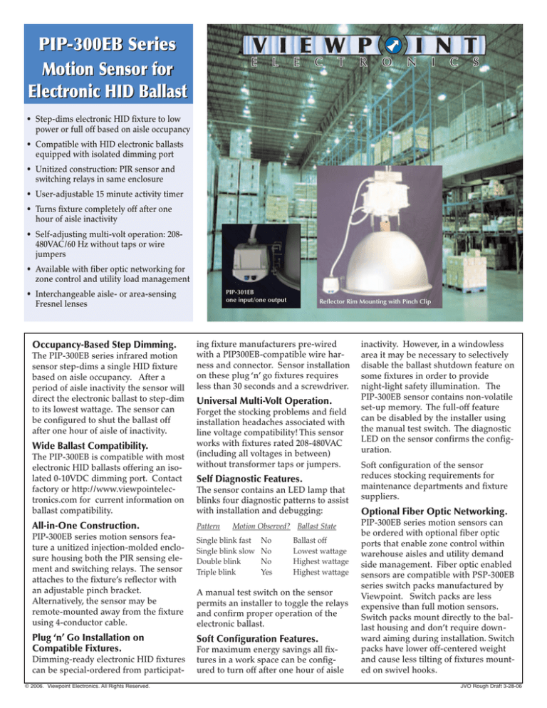
PIP-301EB
one input/one output
• Interchangeable aisle- or area-sensing
Fresnel lenses
Occupancy-Based Step Dimming.
The PIP-300EB series infrared motion
sensor step-dims a single HID fixture
based on aisle occupancy. After a
period of aisle inactivity the sensor will
direct the electronic ballast to step-dim
to its lowest wattage. The sensor can
be configured to shut the ballast off
after one hour of aisle of inactivity.
Wide Ballast Compatibility.
The PIP-300EB is compatible with most
electronic HID ballasts offering an isolated 0-10VDC dimming port. Contact
factory or http://www.viewpointelectronics.com for current information on
ballast compatibility.
All-in-One Construction.
PIP-300EB series motion sensors feature a unitized injection-molded enclosure housing both the PIR sensing element and switching relays. The sensor
attaches to the fixture’s reflector with
an adjustable pinch bracket.
Alternatively, the sensor may be
remote-mounted away from the fixture
using 4-conductor cable.
Plug ‘n’ Go Installation on
Compatible Fixtures.
Dimming-ready electronic HID fixtures
can be special-ordered from participat© 2006. Viewpoint Electronics. All Rights Reserved.
Reflector Rim Mounting with Pinch Clip
ing fixture manufacturers pre-wired
with a PIP300EB-compatible wire harness and connector. Sensor installation
on these plug ‘n’ go fixtures requires
less than 30 seconds and a screwdriver.
Universal Multi-Volt Operation.
Forget the stocking problems and field
installation headaches associated with
line voltage compatibility! This sensor
works with fixtures rated 208-480VAC
(including all voltages in between)
without transformer taps or jumpers.
Self Diagnostic Features.
The sensor contains an LED lamp that
blinks four diagnostic patterns to assist
with installation and debugging:
Pattern
Motion Observed? Ballast State
Single blink fast
Single blink slow
Double blink
Triple blink
No
No
No
Yes
Ballast off
Lowest wattage
Highest wattage
Highest wattage
A manual test switch on the sensor
permits an installer to toggle the relays
and confirm proper operation of the
electronic ballast.
Soft Configuration Features.
For maximum energy savings all fixtures in a work space can be configured to turn off after one hour of aisle
inactivity. However, in a windowless
area it may be necessary to selectively
disable the ballast shutdown feature on
some fixtures in order to provide
night-light safety illumination. The
PIP-300EB sensor contains non-volatile
set-up memory. The full-off feature
can be disabled by the installer using
the manual test switch. The diagnostic
LED on the sensor confirms the configuration.
Soft configuration of the sensor
reduces stocking requirements for
maintenance departments and fixture
suppliers.
Optional Fiber Optic Networking.
PIP-300EB series motion sensors can
be ordered with optional fiber optic
ports that enable zone control within
warehouse aisles and utility demand
side management. Fiber optic enabled
sensors are compatible with PSP-300EB
series switch packs manufactured by
Viewpoint. Switch packs are less
expensive than full motion sensors.
Switch packs mount directly to the ballast housing and don’t require downward aiming during installation. Switch
packs have lower off-centered weight
and cause less tilting of fixtures mounted on swivel hooks.
JVO Rough Draft 3-28-06
7015 Corporate Circle • Indianapolis, Indiana 46278 • www.viewpointelectronics.com • 317.590.0700 • 800.898.7139 • Fax 714.751.8135
SPECIFICATIONS
HID Ballast Compatibility . . . . . . . . . . . . . . . . . . . . . . . . . . . . . . . . . . . . . . . Electronic ballast with 0-10VDC dimming port (consult factory for details)
Compatible with Magnetic Ballasts? . . . . . . . . . . . . . . . . . . . . . . . . . . . . . . . . . . . . . . . . . . . . . . . . No (refer to Model PIP-200 series for magnetic ballast)
Ballast Shutdown Switching Method . . . . . . . . . . . . . . . . . . . . . . . . . . . . . . . . . . . . . . . . . . . . . . . . . . . . . . . . . . . . . . . . . . . . . . . . Relay-switched AC Mains
Shutdown Relay Current Rating . . . . . . . . . . . . . . . . . . . . . . . . . . . . . . . . . . . . . . . . . . . . . . . . . . . . . . . . . . . . . . . . . . . . . . . . . . . . 3 amperes RMS maximum
Maximum Fixture Wattage . . . . . . . . . . . . . . . . . . . . . . . . . . . . . . . . . . . . . . . . . . . . . . . . . . . . . . . . . . . . . . . . . . . . . . . . . . . . . . . . . . . . . . . . . . . . . . . . 450 watts
AC Line Voltage (white and black wires) . . . . . . . . . . . . . . . . . . . . . . . . . . . . . . . . . . . . . . . . . . . . . . . . . . . . . . . . . . . . . . . . . . . . 208/240/277/347/480VAC
Sensor Power Consumption . . . . . . . . . . . . . . . . . . . . . . . . . . . . . . . . . . . . . . . . . . . . . . . . . . . . . . . . . . . . . . . . . . . . . . . . . . . . . . . . . . . . . . . 3 watts maximum
Usable PIR range (@25° C) . . . . . . . . . . . . . . . . . . . . . . . . . . . . . . . . . . . . . . . . . . . . . . . . . . . . . . . . . . . . . . . . . . . . . . . . . . . . . . . . . . . . . . . . . . . . 45 feet on axis
Available Fresnel Lens Patterns . . . . . . . . . . . . . . . . . . . . . . . . . . . . . . . . . . . . . . . . . . . . . . . . . . . . . . . . . . . . . . . . . . Aisle (PIP-30xEB) or Area (PIP-31xEB)
Ambient Temperature Range . . . . . . . . . . . . . . . . . . . . . . . . . . . . . . . . . . . . . . . . . . . . . . . . . . . . . . . . . . . . . . . . . . . . . . . . . . . . . . . . . 0-50° C non-condensing
Observed Motion ON time . . . . . . . . . . . . . . . . . . . . . . . . . . . . . . . . . . . . . . . . . . . . . . . . . . . . . . . . . . . . . . . . . . . . . . . . . . . . . 0-15 minutes (user adjustable)
Ballast Shutdown Time After Inactivity . . . . . . . . . . . . . . . . . . . . . . . . . . . . . . . . . . . . . . . . . . . . . . . . . . . . . . . . . . . . . . . . . . . . . . . . . 1 hour (not adjustable)
Installation Assists . . . . . . . . . . . . . . . . . . . . . . . . . . . . . . . . . . . . . . . . . . . . . . . . . . . . . . . . . . . . . . . . . . . . . . . . . . . . Magnetic Test Switch and Blinking LED
Mounting Options. . . . . . . . . . . . . . . . . . . . . . . . . . . . . . . . . . . . . . . . . . . . . . . . . . . . . . . . . . . . . . . . . . . . . . . . 1/2” NPT nipple or adjustable pinch bracket
Wire Harness . . . . . . . . . . . . . . . . . . . . . . . . . . . . . . . . . . . . . . . . . . . . . . . . . . . . . . . . . . . . . . . . . . . . . . . . . . . . 4 Conductor 18AWG stranded copper STOW
Wire Harness Length . . . . . . . . . . . . . . . . . . . . . . . . . . . . . . . . . . . . . . . . . . . . . . . . . . . . . . . . . . . . . . . . . . . . . . . . . . . . . . . . . . . . . . . . . . . . . . . . . . . . . 36 inches
Harness Termination. . . . . . . . . . . . . . . . . . . . . . . . . . . . . . . . . . . . . . . . . . . . . . . . . . . . . . . . . . . . . . . . . . . . . . . . . . . . Bare wire leads or plug ‘n’ go connector
Off-center Weight. . . . . . . . . . . . . . . . . . . . . . . . . . . . . . . . . . . . . . . . . . . . . . . . . . . . . . . . . . . . . . . . . . . . . . . . . . . 10 ounces without optional counterweight
Dimensions (including mounting nipple). . . . . . . . . . . . . . . . . . . . . . . . . . . . . . . . . . . . . . . . . . . . . . . . . . . . . . . . . . . . . . . . . . . . . . . . . . 3.25” x 3.25” x 3.25”
Environmental Compatibility . . . . . . . . . . . . . . . . . . . . . . . . . . . . . . . . . . . . . . . . . . . . . . . . . . . . . . . . . . . . . . . . . . . . . . . . . . . . . . . . . Indoor Damp Location
UL File Number . . . . . . . . . . . . . . . . . . . . . . . . . . . . . . . . . . . . . . . . . . . . . . . . . . . . . . . . . . . . . . . . . . . . . . . . . . . . . . . . . . . . Category FNFT File No. E234927
Fresnel Lens Floor Patterns
AISLE LENS
BLACK
IN
Typical Fixture
Mounting Configuration
AISLE LENS
BLUE
OUT
AREA LENS
AREA LENS
OPTIONAL COUNTERWEIGHT
Viewpoint products are represented by:
Dual-Output Sensors Interleaved
with Dual-Input Switch Packs
5 Fixture Zone with Pass-Through Switch
Packs and Dual-Output Sensor


