Lab 5 - AC Circuits
advertisement

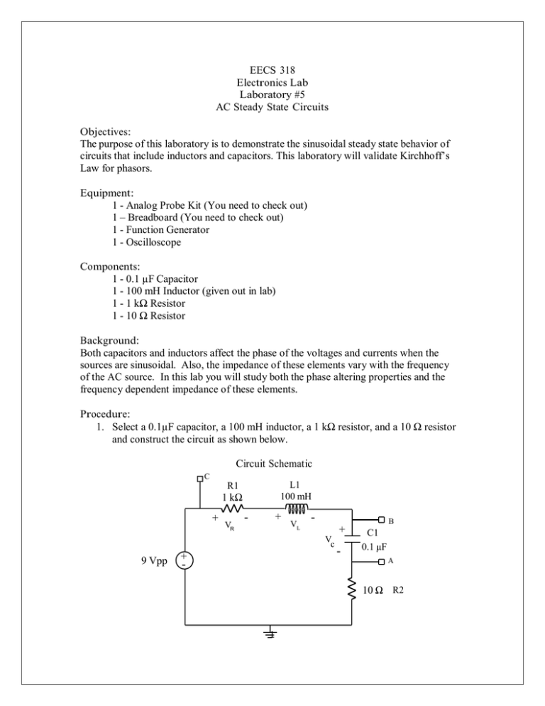
EECS 318 Electronics Lab Laboratory #5 AC Steady State Circuits Objectives: The purpose of this laboratory is to demonstrate the sinusoidal steady state behavior of circuits that include inductors and capacitors. This laboratory will validate Kirchhoff’s Law for phasors. Equipment: 1 - Analog Probe Kit (You need to check out) 1 – Breadboard (You need to check out) 1 - Function Generator 1 - Oscilloscope Components: 1 - 0.1 µF Capacitor 1 - 100 mH Inductor (given out in lab) 1 - 1 kΩ Resistor 1 - 10 Ω Resistor Background: Both capacitors and inductors affect the phase of the voltages and currents when the sources are sinusoidal. Also, the impedance of these elements vary with the frequency of the AC source. In this lab you will study both the phase altering properties and the frequency dependent impedance of these elements. Procedure: 1. Select a 0.1µF capacitor, a 100 mH inductor, a 1 kΩ resistor, and a 10 Ω resistor and construct the circuit as shown below. Circuit Schematic C L1 100 mH R1 1 kΩ + VR - + VL + V c 9 Vpp + - B C1 0.1 µF A - 10 Ω R2 1 2. Set the function generator to produce a sine wave with a frequency of 1 kHz and a Vpp of 9V. 3. First, press default setup on oscilloscope to ensure that default settings are turn on. Next, select AC coupling for both channels. Set both channels of the oscilloscope to “BW limit-on.” This will filter out noise from unwanted signal sources in the room, such as computers. 4. Next, add the following measurements to the oscilloscope display. Press the measurement button, select Ch 1 under source, select “Pk-Pk” under Type and then select Add measurement. Repeat the same steps for adding Peak-Peak measurements for Ch 2. Finally, add the “Phase” measurement under Type for Ch 1. 5. Connect the Ch 2 input of the oscilloscope to point A and the ground clip to the circuit ground (the bottom node). This will allow the oscilloscope to monitor the voltage across the 10Ω resistor. This voltage drop across this resistor will be small compared to the other drops in the loop, but will allow you to monitor the current of the circuit on the oscilloscope. Measure the peak-peak amplitude of the voltage across the 10Ω resistor. Calculate the peak amplitude of the current, which is the magnitude of the current. Q1: What is the magnitude of the current, |I|? 7. Next, connect the Ch 1 input of the oscilloscope to point B, leaving the ground clip at the circuit ground. This makes Ch 1 the voltage drop across the 0.1µF capacitor and the 10 Ω resistor, but since the drop across the 10 Ω resistor is small, this voltage is basically the voltage across the capacitor, VC. Note: Since both the oscilloscope ground and the function generator ground are both connected to “physical ground,” it is important that both of these grounds are connected to the same point in the circuit. 8. Measure the magnitude |VC|. Also, measure phase φC relative to the current waveform of Ch 2. To measure the phase, select phase from the time menus on the oscilloscope. Q2: What is the magnitude and phase of the voltage across the capacitor, |VC| and φC? 2 9. While keeping the oscilloscope probes at the same locations, switch off the function generator and then exchange the positions of the capacitor and the inductor and repeat the above measurements for the inductor. In this way, Ch 1 now represents the voltage VL across the inductor. After switching on the function generator again, using the procedure in step 6, measure the values of |VL| and φL. Note: Real capacitors and inductors are not ideal so don't expect the lead or lag to be exactly ±90°, particularly for the inductor. Q3: What is the magnitude and phase of the voltage across the inductor, |VL| and φL? 10. Switch off the function generator, exchange the inductor and the 1 kΩ resistor and repeat the above measurements for the resistor after switching on the function generator. These measurements are |VR| and φR. Q4: What is the magnitude and phase of the voltage across the inductor, |VR| and φR? 11. Connect the CH 1 input to the output of the function generator by leaving the circuit intact and connecting the lead to point C. These measurements are the circuit measurements V and φ. Q5: What is the magnitude and phase of the supply voltage, |V| and φ? 10. Draw VC, VL, and VR to scale on a phasor diagram using the space below. Add these three vectors using a vector sum (magnitude and scale) within the same phasor diagram. Support your drawing with calculations to obtain the supply voltage, |V| and φ (formulas provided on the whiteboard). Q6: Is the vector sum of the VC, VL, and VR approximately equal to V? 3 11. Also, using your measured data and Ohm’s law in phasor form, calculate the impedance (magnitude and phase) of the resistor, inductor, and capacitor and compare these values with the values predicted from the component values at the frequency of operation. Q7: Using the measurements, what is the experimental impedance (magnitude and phase) of the capacitor, inductor and resistor, ZC, ZL, and ZR? Q8: Using the values of the components, what is the theoretical impedance (magnitude and phase) of the capacitor, inductor and resistor, ZC, ZL, and ZR? f |VC| φC |VL| φL 1.0 kHz 4 |VR| φR |V| φ


