Datasheet
RE-RIBD0XBDC Series
Dry Contact Time Delay Relays
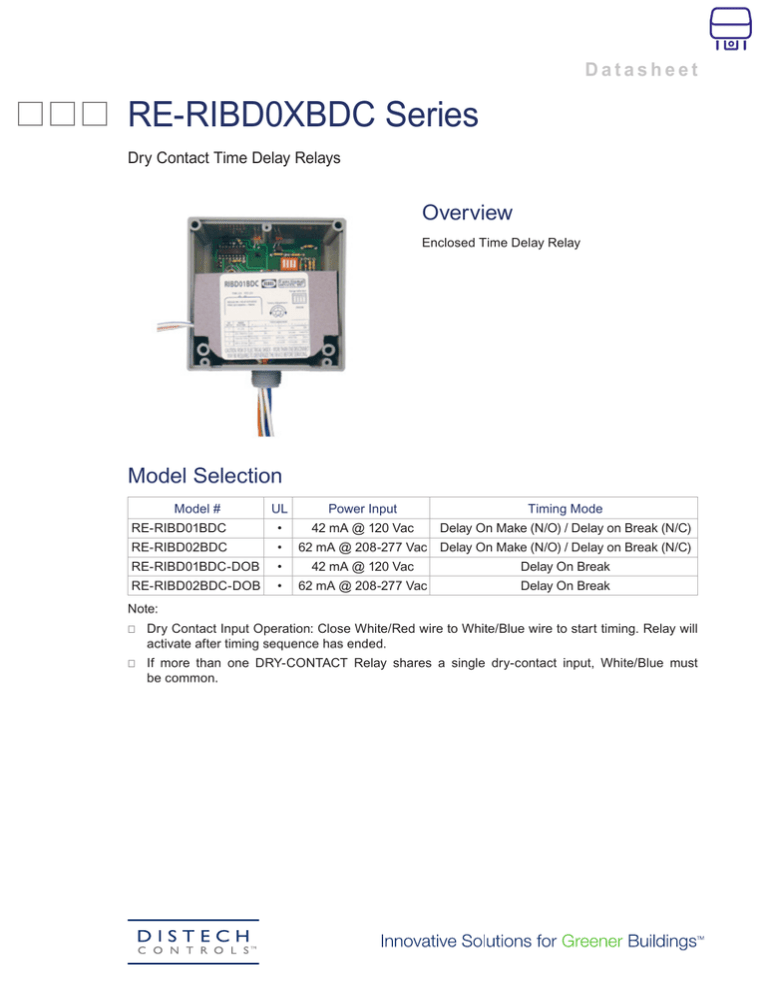
Overview
Enclosed Time Delay Relay
Model Selection
Model #
UL
Power Input
Timing Mode
42 mA @ 120 Vac
Delay On Make (N/O) / Delay on Break (N/C)
RE-RIBD01BDC
•
RE-RIBD02BDC
•
RE-RIBD01BDC-DOB
•
42 mA @ 120 Vac
Delay On Break
RE-RIBD02BDC-DOB
•
62 mA @ 208-277 Vac
Delay On Break
62 mA @ 208-277 Vac Delay On Make (N/O) / Delay on Break (N/C)
Note:
⎕⎕ Dry Contact Input Operation: Close White/Red wire to White/Blue wire to start timing. Relay will
activate after timing sequence has ended.
⎕⎕ If more than one DRY-CONTACT Relay shares a single dry-contact input, White/Blue must
be common.
Product Specifications
Relay Coil—————————————————————————————————————————————————— Continuous Duty Coil
Expected Relay Life——————————————————————————————— 10 million cycles minimum mechanical
Operating Temperature—————————————————————————————————————————————— -30 to 140° F
Humidity Range——————————————————————————————————————————— 5 to 95% (noncondensing)
Operate Time——————————————————————————————————————————————— 18mS after time delay
Relay Status—————————————————————————————————————————————— Red LED On = Activated
Time Delay Status——————————————————————— Pink LED FLASHING = Timing / Relay Deactivated
Timing Range—————————————————————————————————————————————— 6 seconds - 20 minutes
Timing Adjustment—————————————————————— 4 position DIP switch for range selection and single
—————————————————————————————————— turn potentiometer for timing adjustment within range
Timing Tolerance———————————————————————————————————————————— Switches 1 & 2 = +10%
————————————————————————————————————————————————————————— Switches 3 & 4 = +5%
Timing Repeatability——————————————————————————————————————————————————————— +1%
Temperature Timing Variance————————————————————————————————————————————————— +1%
Voltage Timing Variance———————————————————————————————————————————————————— +1%
Recycle Time—————————————————————————————————————————————————— 750ms Maximum
Dimensions——————————————————————————————————— 4.00˝ x 4.00˝ x 1.80˝ with .50˝ NPT nipple
Wires————————————————————————————————————————————————————————— 16˝, 600V Rated
Approvals—————————————————— UL Listed, UL916, C-UL, California State Fire Marshal, CE, RoHS
Housing Rating———————————————————————————————— UL Accepted for Use in Plenum, NEMA 1
Gold Flash——————————————————————————————————————————————————————————————— No
Override Switch———————————————————————————————————————————————————————————— No
Number of Relays——————————————————————————————————————————————————————————— 1
Relay Form————————————————————————————————————————————————————————————— SPDT
No / NC————————————————————————————————————————————————————————————— NO & NC
Contact Ratings:
⎕⎕ ——————————————————————————————————————————————————20 Amp Resistive @ 277 Vac
⎕⎕ ——————————————————————————————————————————— 20 Amp Ballast1 @ 120/277 Vac (N/O)
⎕⎕ ——————————————————————————————————————————— 10 Amp Ballast1 @ 120/277 Vac (N/C)
⎕⎕ ————————————————————————————————————————————— 10 Amp Tungsten @ 120 Vac (N/O)
⎕⎕ —————————————————————————————————————————————————— 770 VA Pilot Duty @ 120 Vac
⎕⎕ —————————————————————————————————————————————————1,110 VA Pilot Duty @ 277 Vac
⎕⎕ ——————————————————————————————————————————————————————————— 2 HP @ 277 Vac
⎕⎕ ——————————————————————————————————————————————————————————— 1 HP @ 120 Vac
1. Not rated for Electronic Ballast
2/4
RE-RIBD0XBDC Series
Time Delay Adjustment
RE-RIBD0XBDC Series
3/4
Timing Diagram for RE-RIBD01BDC & RE-RIBD02BDC
Timing Diagram for RE-RIBD01BDC-DOB & RE-RIBD02BDC-DOB
Specifications subject to change without notice.
Distech Controls, and the Distech Controls logo are trademarks of Distech Controls Inc. All other trademarks are property of their respective owner.
©, Distech Controls Inc., 2015. All rights reserved.
4/4
05DI-DSRERBD-10


