solid state ignition
advertisement

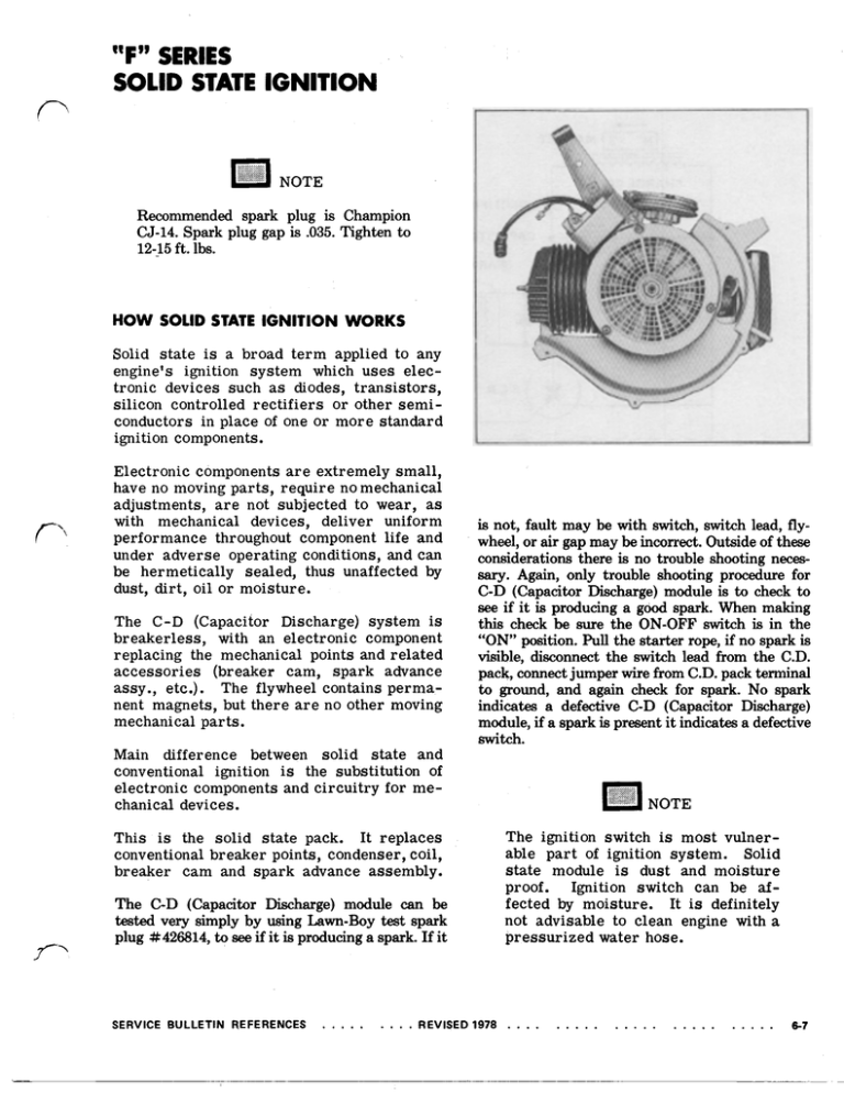
“F” SERIES SOLID STATE IGNITION Recommended spark plug is Champion CJ-14. Spark plug gap is .035.Tighten to 12-15ft. lbs. HOW SOLID STATE IGNITION WORKS Solid state is a broad term applied to any engine’signition system which useselectronicdevicessuch as diodes,transistors, silicon controlled rectifiers or other semiconductors in place of one or more standard ignition components. Electronic components are extremely small, have no moving parts, require nomechanical adjustments, are not subjected to wear, as with mechanicaldevices,deliveruniform performancethroughoutcomponentlifeand under adverse operating conditions, and can behermeticallysealed,thusunaffected by dust, dirt, oil or moisture. is The C-D (CapacitorDischarge)system breakerless, with anelectroniccomponent replacing the mechanical points and related accessories(breakercam,sparkadvance assy.,etc.).Theflywheelcontains permanent magnets, but there are no other moving mechanical parts. is not, fault may be with switch, switch lead, flywheel, or air gap may be incorrect. Outside of these considerations there is no trouble shooting necessary. Again, only trouble shooting procedure for C-D (Capacitor Discharge) module is to check to see if it is producing a good spark. When making this check be sure the ON-OFF switch is in the “ON” position. Pull the starter rope, if no spark is visible, disconnect the switch lead from the C.D. pack, connect jumper wire from C.D. packterminal to ground, and again checkfor spark. No spark indicates a defective C-D (Capacitor Discharge) module, if a spark is present it indicates a defective switch. Main difference between solid state and is thesubstitution of conventionalignition electronic components and circuitry for mechanical devices. NOTE Theignitionswitch is most vulnerable part of ignition system. Solid state module is dustandmoisture proof. Ignition switch can be affected by moisture.It is definitely not advisable to clean engine with a pressurized water hose. This is thesolidstate pack. Itreplaces conventional breaker points, condenser, coil, breakercamandsparkadvanceassembly. The C-D (Capacitor Discharge)module can be tested very simply by using Lam-Boy test spark plug #426814, to see if it is producing a spark. If it SERVICE BULLETIN REFERENCES REVISED 1978 6-7 "F" SERIES (Cont.) As flywheel magnets pass solid state module laminations, a low voltage alternating current i s induced into charge coil. MAGNET CHARGE COIL RECTIFIER CAPACITOR I A SPARK COIL I IGNITION SWITCH I This alternating current passes through a *][ recifier, transforming it into directcurrent. Current i s then stored in capacitor. MAGNET RECTIFIER CAPACITOR SPARK COIL SPARK PLUG IGNITION SWITCH 6-8 SERVICEBULLETINREFERENCES “F” SERIES (Cont.) POLE SHOE RTING LEG ROTATION CRANKSHAFT A T 5’ BTDC Flywheel magnets rotate approximately 355’ until they pass laminations, inducing a small electrical charge into trigger coil. At this charge has proper starting speeds, magnitudetoturn on thesiliconcontrolled rectifier (solid state switch) at retarded position for easy starting. This is illustrated a s 5” 6’ retardfiringposition. SERVICEBULLETINREFERENCESREVISED 1978 6-9 “F” SERIES (Cont.) Whenenginereachesapproximately 800 revolutions per minute, advance firing commences. Flywheelmagnetstravelapproximately 335°at which time enough voltage is induced to trigger coil to fire thesiliconcontrolledrectifier(solidstate switch).See advanced firing position 24°-27° UNNlNG LEG 5” ADVANCE FLYWHEEL ROTATION CRANKSHAFT AT 25” BTDC Whenthe silicon controlled rectifier is triggered, up to 300 voltsstored in capacitor travel tospark coil where it i s stepped up instantaneously to a maximum of 30,000 volts and discharged acrosselectrodes of spark plug. MAGNET CHARGE COIL RECTIFIER I SPARK COIL SPARK PLUG I 6-10 IGNITION SWITCH REVISED 1978. SERVICEBULLETINREFERENCES “F” SERIES (Cont.) 1. Flywheel and solid state module pack can be exposed very easily by removing air baffle from shroud,fuelhosesand shroudbase.Removekillswitchlead from ignition switch. 2. Clearance is obtained by rotatingthe flywheeluntilflywheelmagnets are adjacenttothesolid state pack as illustrated. CORRECT AIR GAP IS .010. : NOTE Use Lawn-Boy Air Gap Gauge Part No. 604659. 3 . Insertnon-metallicgauge betweenC-D packlaminationsandmagnets(magnets will pullthe C-D packintightly). Two screwssecuring module a r e then tightened. The .010 gap is s e t between two square legs of laminationsandmagnets. The charging leg of the lamination will be further from the flywheel since curvature of laminationsdoes not conformtothat of flywheel. FLYWHEELREPLACEMENT 1. Remove spark plugandinstallPiston Stop Part No. 677389. Removeshroud, fuelhosesand air bafflefromshroud base. 951 19 SERVICE BULLETIN REFERENCES REVISED 2. Using a socket wrench, remove flywheel nut.Remove flywheelscreen. 1978 6-11 "F" SERIES (Cont.) 3. Place fingers under flywheel screen and apply upward pressure. At the same time, strike wide fin of flywheel with a soft headed hammertobreakflywheel loose as shown. MAKE SURE KEY IS INSTALLED CORRECTLY RIGHT WRONG 4. Remove flywheel.Afterremovingflywheel, note position of flywheel key. Key must be installed withthestraight edge in a vertical (straight up and down) position. It should not be installed with straight edge parallel to the crankshaft taper. Removekey with a pair of side cutters or dikes. 5. Checkflywheel for wear and strength of flywheel magnets. Check keyway for distortion and/or cracks. 6. Flywheel nut should always be torqued properly when flywheelis reinstalled. Correct torque is 375 400 inch pounds (31 33 ft. lbs.). Fly- wheel hub and crankshaft taper must be a h lutely clean - void of grease and oil. "F" SERIES (Cont.) TROUBLE SHOOTING THE "F" ENGINE IGNITION SYSTEM Mis-firing, no fire, engine dying, o r surging may sometimes be traced to the ignition system. If normal trouble shooting procedures fail to eliminate these symptoms, then the ignitionsystemshouldbecheckedusing thefollowingguidelines; it is possible that a defective switch o r improper C.D. module groundcould alsocausetheseproblems. 1. Attach the Test Plug Part No. 426814 to the high tension lead and ground plug to a cylinder fin. The "F" engine C.D. pack must be grounded to run. 6 inchjumperwire (18 ga. o r larger) to the lower terminal of the C.D. module. (This is theterminal molded into the plastic casing of the C.D. pack). Ground the other end to the cylinder fin. Do notloop existing C.D. pack ground wire to this terminal. 3. If good spark is evident when cranked, C.D. module is operatingproperly. Remove jumper from cylinder fin andground it totheend of the C.D. pack ground lead pig tail at the outer end. If good spark is still evident when cranked, then the switch is possibly defective and should be replaced. 4. If no spark is evident when attaching test leadto C.D. pack groundwire, o r if engine fires intermittently, remove C. D. pack. Look for a bad connection o r a broken ground lead. Clean both sides of the C.D. pack mounting bosses with sandpaper ora scraper. 2. Attacha SERVICE BULLETIN REFERENCES 5. Alsocheck for secure attachment of the high tensionlead. This leadshould be secured with OMC Adhesive "M" P a r t No. 318535 o r G.E. Silicon Sealant. 6-13 C-D PACKS D-600 SERIES F-SERIES PART NO. 681542 MANUAL START F SERIES C-D PACK CLOSED TO RUN TYPE SYSTEM USED ON 1978 THRU 1982 MODELS. These “F” Series C-D modules are not interchangeable with D-600 Series C-D modules. PART NO. 681544 ELECTRIC START SELF CHARGING PART NO. 683215 GRAY USED ON 1983 AND LATER COMPLIANT LAWN MOWERS. I PART NO. 681546 ELECTRIC START OPEN TO RUN TYPESYSTEMUSED COMPLIANT MOWERS. ON ALL


