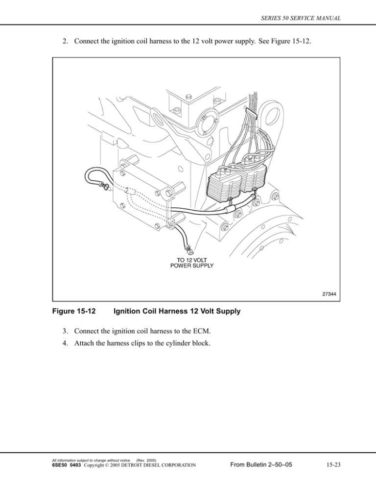
2. Connect the ignition coil harness to the 12 volt power supply. See
advertisement

SERIES 50 SERVICE MANUAL 2. Connect the ignition coil harness to the 12 volt power supply. See Figure 15-12. Figure 15-12 Ignition Coil Harness 12 Volt Supply 3. Connect the ignition coil harness to the ECM. 4. Attach the harness clips to the cylinder block. All information subject to change without notice. (Rev. 2005) 6SE50 0403 Copyright © 2005 DETROIT DIESEL CORPORATION From Bulletin 2–50–05 15-23 15.10 SPARK PLUGS 15.10 SPARK PLUGS The condition of the spark plug determines the high voltage level and is the single most important component of the ignition system. The size of the electrode gap, conditions of the electrodes, and the amount of deposits on the electrode all affect the life of the plug. The electrodes of the spark plug are made from platinum or iridium which will minimize electrode wear. The spark plug gap can be regapped if the wear and amount of deposits are low. If either condition is excessive, replace the spark plug. For engine model 6047-TKG8 measure the spark plug gap using a 0.381 mm (0.015 in.) feeler gage. Effective with engine serial number 04R0045632 model 6047-MKG8 measure the spark plug gap using a 0.254 mm (0.010 in.) feeler gage. NOTE: Servicing of the spark plugs should take place while the engine is cool. This will facilitate easier removal of the spark plugs and reduce the possibility of the plug sticking in the spark plug insert contained in the cylinder head; this also ensures the correct torque and eliminates damage to the spark plug and gasket during installation of the plugs. 15.10.1 Removal of Spark Plug Remove the spark plugs from the cylinder head as follows: 1. Disconnect the ignition wires from the ignition boots. 2. Remove the ignition boots from the spark plug wells by rotating the boot until the boot slots clear the retainer tangs. 3. Remove the plug using a 5/8 in. thin wall spark plug socket and appropriate extensions. 15.10.1.1 Cleaning of Spark Plug Terminal, Ceramic Insulation, and Socket Area Clean the spark plug terminal, ceramic insulation, and spark plug socket as follows: EYE INJURY To avoid injury from flying debris when using compressed air, wear adequate eye protection (face shield or safety goggles) and do not exceed 276 kPa (40 psi) air pressure. 1. Remove dirt and debris with compressed air. 2. Remove oil and grease deposits. 3. Inspect the spark plug. (Rev. 2005) 15-24 From Bulletin 2–50–05 All information subject to change without notice. 6SE50 0403 Copyright © 2005 DETROIT DIESEL CORPORATION SERIES 50 SERVICE MANUAL 15.10.1.2 Inspection of Spark Plug Inspect the spark plug as follows: 1. For engine model 6047-TKG8 measure the spark plug gap using a 0.381 mm (0.015 in.) feeler gage. Effective with engine serial number 04R0045632 model 6047-MKG8 measure the spark plug gap using a 0.254 mm (0.010 in.) feeler gage. [a] If the spark plug gap measured is not to specifications, re-gap the plug and use again. Refer to Section 15.10.2. [b] If the spark plug gap is within specifications, use the spark plug again. Refer to Section 15.10.2 2. Visually check the spark plugs for excessive deposits and condition of the electrode. [a] If the spark plug has excessive deposits and electrode wear, replace the spark plug. Refer to Section 15.10.2. [b] If the spark plug has no deposits nor excessive electrode wear, use the spark plug again. Refer to Section 15.10.2. 15.10.2 Installation of Spark Plug Install the spark plug as follows: 1. Install the spark plug using a 5/8 in. thin wall socket and appropriate extensions. Torque the spark plug to 35 - 41 N·m (26-30 lb·ft). 2. Install the ignition boot. Refer to Section 15.5.2. 3. Install the ignition harness. Refer to Section 15.3.2. All information subject to change without notice. (Rev. 2005) 6SE50 0403 Copyright © 2005 DETROIT DIESEL CORPORATION From Bulletin 2–50–05 15-25 15.11 COIL OVER PLUG IGNITION SYSTEM 15.11 COIL OVER PLUG IGNITION SYSTEM Series 50G engines produced after July 1996 and all genset engines use the coil over plug ignition system. This system consists of four coils, four ignition boots, mounting screws and seals, an ignition module, an igniter module bracket, an ignition coil harness, a ground strap, and four spark plugs. The coils mount in the rocker cover directly above the spark plugs. A coil cover mounts in the rocker cover which protects the coils and shields electromagnetic radiation (EMR) from the environment. See Figure 15-13. (Rev. 2005) 15-26 From Bulletin 2–50–05 All information subject to change without notice. 6SE50 0403 Copyright © 2005 DETROIT DIESEL CORPORATION


