Installation Guidelines
advertisement
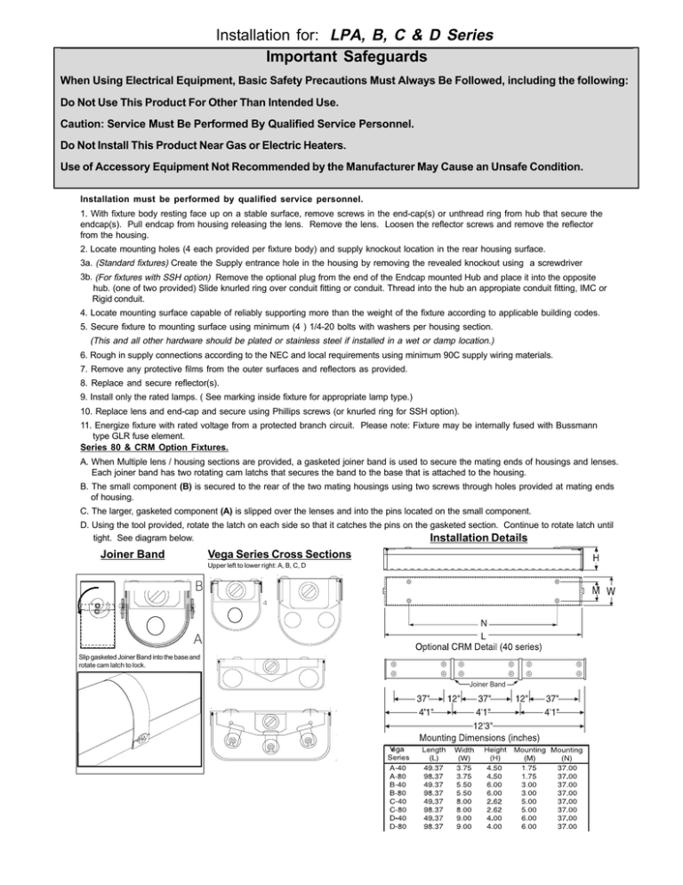
Installation for: LPA, B, C & D Series Important Safeguards When Using Electrical Equipment, Basic Safety Precautions Must Always Be Followed, including the following: Do Not Use This Product For Other Than Intended Use. Caution: Service Must Be Performed By Qualified Service Personnel. Do Not Install This Product Near Gas or Electric Heaters. Use of Accessory Equipment Not Recommended by the Manufacturer May Cause an Unsafe Condition. Installation must be performed by qualified service personnel. 1. With fixture body resting face up on a stable surface, remove screws in the end-cap(s) or unthread ring from hub that secure the endcap(s). Pull endcap from housing releasing the lens. Remove the lens. Loosen the reflector screws and remove the reflector from the housing. 2. Locate mounting holes (4 each provided per fixture body) and supply knockout location in the rear housing surface. 3a. (Standard fixtures) Create the Supply entrance hole in the housing by removing the revealed knockout using a screwdriver 3b. (For fixtures with SSH option) Remove the optional plug from the end of the Endcap mounted Hub and place it into the opposite hub. (one of two provided) Slide knurled ring over conduit fitting or conduit. Thread into the hub an appropiate conduit fitting, IMC or Rigid conduit. 4. Locate mounting surface capable of reliably supporting more than the weight of the fixture according to applicable building codes. 5. Secure fixture to mounting surface using minimum (4 ) 1/4-20 bolts with washers per housing section. (This and all other hardware should be plated or stainless steel if installed in a wet or damp location.) 6. Rough in supply connections according to the NEC and local requirements using minimum 90C supply wiring materials. 7. Remove any protective films from the outer surfaces and reflectors as provided. 8. Replace and secure reflector(s). 9. Install only the rated lamps. ( See marking inside fixture for appropriate lamp type.) 10. Replace lens and end-cap and secure using Phillips screws (or knurled ring for SSH option). 11. Energize fixture with rated voltage from a protected branch circuit. Please note: Fixture may be internally fused with Bussmann type GLR fuse element. Series 80 & CRM Option Fixtures. A. When Multiple lens / housing sections are provided, a gasketed joiner band is used to secure the mating ends of housings and lenses. Each joiner band has two rotating cam latchs that secures the band to the base that is attached to the housing. B. The small component (B) is secured to the rear of the two mating housings using two screws through holes provided at mating ends of housing. C. The larger, gasketed component (A) is slipped over the lenses and into the pins located on the small component. D. Using the tool provided, rotate the latch on each side so that it catches the pins on the gasketed section. Continue to rotate latch until tight. See diagram below. Installation Details Joiner Band Vega Series Cross Sections Upper left to lower right: A, B, C, D B 4 4 A Slip gasketed Joiner Band into the base and rotate cam latch to lock. Joiner Band 4
