(1mark)
K.C.S.E 2012 PHYSICS PAPER 2
SECTION A (25 marks) Answer ALL the questions in this section in the spaces provided
.
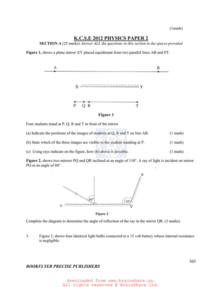
Figure 1, shows a plane mirror XY placed equidistant from two parallel lines AB and PT.
Four students stand at P, Q, R and T in front of the mirror
(a) Indicate the positions of the images of students at Q, R and T on line AB.
(1 mark)
(b) State which of the three images are visible to the student standing at P.
(1 mark)
(c) Using rays indicate on the figure, how (b) above is possible.
(1 mark)
Figure 2, shows two mirrors PQ and QR inclined at an angle of 110°. A ray of light is incident on mirror
PQ at an angle of 60°.
Complete the diagram to determine the angle of reflection of the ray in the mirror QR. (3 marks)
3.
Figure 3, shows four identical light bulbs connected to a 15 volt battery whose internal resistance
is negligible.
365
BOOKFLYER PRECISE PUBLISHERS
downloaded from www.brainshare.ug.
All rights reserved @ BrainShare Ltd.
Determine the reading of the voltmeter V.
4.
Figure 4, shows a negative point charge placed near a positively charged rod.
Draw on the diagram, the resulting electric field pattern.
5.
(2marks)
(2marks)
Figure 5, shows an object O at the bottom of a beaker full of a liquid. An observer above the
beaker sees its image at point X inside the liquid.
366
BOOKFLYER PRECISE PUBLISHERS
downloaded from www.brainshare.ug.
All rights reserved @ BrainShare Ltd.
Determine the refractive index of the liquid.
6.
(3marks)
Figure 6, shows a narrow beam of radiation from a radioactive sources, incident to a postcard.
The emergent radiation passes through a magnetic field which is perpendicular to the plane of the
paper, and into the paper.
A detector moved along line AC detects radiations only at points B and C. State the two
types of radiation detected.
(1mark)
367
BOOKFLYER PRECISE PUBLISHERS
downloaded from www.brainshare.ug.
All rights reserved @ BrainShare Ltd.
7.
Figure 7, shows two similar coils P and Q around the end L and M of a piece of soft iron.
A steady current passes through the coils.
State the polarity of the resulting magnet at end L.
(1mark)
8.
Light from a lamp falls on the cap of a negatively charged electroscope. It is observed
that the divergence of the leaf decreases. Explain the observation.
(2 marks)
9.
Figure 8, shows an object O placed in front of a diverging lens whose principal focus is
F.
On the figure, draw a ray diagram to locate the image formed.
(3marks)
368
BOOKFLYER PRECISE PUBLISHERS
downloaded from www.brainshare.ug.
All rights reserved @ BrainShare Ltd.
10.
11.
Figure 9, shows the cross-section of an optical fibre made of two types of glass. A and B.
The refractive index of B is lower than that of A.
A ray of light enters the optical fibre at P and emerges from Q.
i) Sketch the path of the ray through the fibre.
(1mark)
ii) State the reason why light travels through the fibre as in (i) above.
(1mark)
Figure 10. Shows the cross section of a conductor held between two magnets and
carrying a current out of the paper.
Indicate with an arrow on the diagram the direction in which the conductor will move
when it is released.
(1mark)
12.
State why alternating current (a.c.) is used for transmitting electricity over long distances.
(1marks)
13.
Figure 11, shows an alternating current (a.c) connected across a diode D and a resistor R.
369
BOOKFLYER PRECISE PUBLISHERS
downloaded from www.brainshare.ug.
All rights reserved @ BrainShare Ltd.
On the axes provided sketch the output as observed in the C.R.O. connected across R.
(1mark)
SECTION B (55 marks)
Answer All the questions in this section in the spaces provided.
14. a) Figure 12, shows a displacement – time graph for a progressive wave.
370
BOOKFLYER PRECISE PUBLISHERS
downloaded from www.brainshare.ug.
All rights reserved @ BrainShare Ltd.
i)
State the amplitude of the wave.
(1 mark)
ii)
Determine the frequency of the waves
(4marks)
iii)
Given that the velocity of the wave is 20ms-1, determine its wavelength. (3marks)
b)
Figure 13, shows two identical dippers A and B vibrating in water in phase with each
other. The dippers have the same constant frequency and amplitude. The waves produced
are observed along the MN;
It is observed that the amplitudes are maximum at points Q and S, and minimum at points
P and R.
15.
i) Explain why the amplitude is maximum at Q.
(2marks)
ii) State why the amplitude is minimum at R.
(1mark)
iii) State what would happen if the two dippers had different frequencies
(1mark)
Figure 14, shows a circuit in which a battery, a switch, a bulb, a resistor P, a variable
resistor Q, a voltmeter V and two ammeters A1 and A2 of negligible resistance are
connected.
371
BOOKFLYER PRECISE PUBLISHERS
downloaded from www.brainshare.ug.
All rights reserved @ BrainShare Ltd.
P has a resistance of 10Ω . When the switch is closed, A1 reads 0.10A and the voltmeter
reads 1.5V.
a)
b)
c)
Determine;
i) the current passing through P;
(3marks)
ii) the resistance of the bulb.
(2marks)
The variable resistor Q is now adjusted so that a larger current flows through A2.
i) State how this will affect the resistance of the bulb
(1mark)
ii) Explain your answer in b) (i)
(2marks)
A house has one 100W bulb. Two 60W bulbs and one 30W bulb. Determine the cost of
having all the bulbs switched on for 70 hours, given that the cost of electricity is 40cents
per kilowatt hour.
(3marks)
16. a) Figure 15, shows two coils A and B placed close to 3each other. A is connected to a
steady D.C. supply and a switch, B is connected to a sensitive galvanometer.
372
BOOKFLYER PRECISE PUBLISHERS
downloaded from www.brainshare.ug.
All rights reserved @ BrainShare Ltd.
i)
The switch is now closed, state the observation made on the galvanometer. (2marks)
ii)
Explain what would be observed if the switch is then opened.
b)
The primary coil of a transformer has 1000 turns and the secondary coil has 200 turns.
The primary coil is connected to a 240V ac. Mains supply.
(2marks)
i) Eplain how an e.m.f induced in the secondary coil.
(2marks)
ii)Determine the secondary voltage.
(3marks)
iii) Determine the efficiency of the transformer given that the current in the primary coil
is 0.20A and in the secondary coil it is 0.80A.
(3marks)
17. a) Figure 16, shows a graph of magnification against object distance, for an object placed in
front of a lens of focal length 20cm.
373
BOOKFLYER PRECISE PUBLISHERS
downloaded from www.brainshare.ug.
All rights reserved @ BrainShare Ltd.
Using the graph;
i) State the effect on the size of the image when the object distance is increased from
25cm.
(1mark)
ii) Determine the distance between the object and the lens when the image is the same
size as the object.
(2marks)
iii)Determine the image distance when the object distance is 25cm.
(3marks)
b) Figure 17 shows an object O placed in front of a converging mirror of focal length 15cm.
374
BOOKFLYER PRECISE PUBLISHERS
downloaded from www.brainshare.ug.
All rights reserved @ BrainShare Ltd.
Draw on the figure a ray diagram to locate the image formed.
(3marks)
c)
State why parabolic reflectors are used in car headlights.
(1mark)
18.
Figure 18 shows the parts of an x-ray tube.
a)
Explain why;
i) A potential difference is applied to the filament.
(2marks)
ii) A high potential difference is applied between the cathode and the anode. (2 marks)
iii) Most of the tube is surrounded by lead.
(1mark)
375
BOOKFLYER PRECISE PUBLISHERS
downloaded from www.brainshare.ug.
All rights reserved @ BrainShare Ltd.
b)
State how the resulting x-rays are affected by increasing the potential difference between
the anode and the cathode.
(1mark)
c)
Light of frequency 7.5 x 10¹⁴ HZ strikes a metal surface whose work function is
4.0 x 10⁻¹⁹J. Determine the kinetic energy of the emitted photoelectrons.
(take planks constant h = 6.63 x 10⁻³⁴Js)
(4marks)
K.C.S.E 2012 PHYSICS PAPER 3
PRACTICAL
Question 1
You are provided with the following;
- Two biconvex lenses labeled A and B.
- A light source.
- Screen I with a hole and cross wire at its centre
- Screen II
- A metre rule.
- A plane mirror.
- A piece of cellotape.
- Two lens holders.
- A stand, boss and clamp
Proceed as follows;
Use the stand to hold the light source in line with the crosswires on screen I and lens A with the
plane mirror as shown in figure 1.
Adjust the position or the lens with the mirror until a sharp image of the cross wires is found on
screen I beside the crosswires. Measure the distance between the screen and lens A.
1 between the screen and lens A.
1=________________________
376
BOOKFLYER PRECISE PUBLISHERS
downloaded from www.brainshare.ug.
All rights reserved @ BrainShare Ltd.

