3B18 Wide-Bandwidth, Strain Gage Input
Functional Description
Input and Output Ranges
Available Models
Specifications
3B Series Overview
Backplanes
Power Supplies
Accessories
Ordering Guide
Functional Description
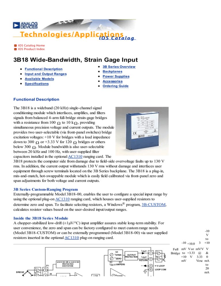
The 3B18 is a wideband (20 kHz) single-channel signal
conditioning module which interfaces, amplifies, and filters
signals from balanced 4-arm full-bridge strain-gage bridges
to 10 k , providing
with a resistance from 100
simultaneous precision voltage and current outputs. The module
provides two user-selectable (via front-panel switches) bridge
excitation voltages: +10 V for bridges with a load impedance
down to 300 or +3.33 V for 120 bridges or others
below 300 . Module bandwidth is also user-selectable
between 20 kHz and 100 Hz, with user-supplied filter
capacitors installed in the optional AC1310 ranging card. The
3B18 protects the computer side from damage due to field-side overvoltage faults up to 130 V
rms. In addition, the current output withstands 130 V rms without damage and interfaces user
equipment through screw terminals located on the 3B Series backplane. The 3B18 is a plug-in,
mix-and-match, hot-swappable module which is easily field calibrated via front-panel zero and
span adjustments for both voltage and current outputs.
3B Series Custom-Ranging Program
Externally-programmable Model 3B18-00, enables the user to configure a special input range by
using the optional plug-on AC1310 ranging card, which houses user-supplied resistors to
determine zero and span. To facilitate selecting resistors, a Windows® program, 3B-CUSTOM,
calculates resistor values based on the user-desired input/output ranges.
Inside the 3B18 Series Module
A chopper-stabilized low-drift (±1µV/°C) input amplifier assures stable long-term stability. For
user convenience, the zero and span can be factory configured to meet custom range needs
(Model 3B18-CUSTOM) or can be externally programmed (Model 3B18-00) via user supplied
resistors inserted in the optional AC1310 plug-on ranging card.
-10 +10.0
3
-10
V
to
+10
Full mV V or mV/V V
Bridge to +3.33 @ &
+10 V 3.33 0
mV
Vexc mA
to
20
mA
Figure 1. 3B18 Functional Block Diagram
Figure 2. 3B18 Input Field Connections
Input Type
Dual Outputs
Strain Gage:
Full 4-Arm Bridge
-10 V to +10 V
4 mA to 20 mA or 0 to 20 mA
3B18 Models Available
Model Input Input
Bridge Range
Excitation 1
3B18-00 Full
Externally
Bridge Programmable3
+10.0 V or +3.33 V Externally
Sensitivity
Programmable
Output
Ranges
3
-10 V to +10 V &
0 mA to 20 mA
3B18-01 Full
-30 mV to +30 mV +10.0 V or +3.33 V 3 mV/V @ 10 Vexc -10 V to +10 V &
Bridge
0 mA to 20 mA
3B18-02
3B18-Custom
1
Full
Bridge
Output current range may be user programmed to 4 mA to 20 mA using jumper supplied.
2
Requires AC1310 ranging card.
*Custom Input/Output ranges are available. Refer to ordering guide.
3B18 Specifications
(typical @ +25°C and ±15 V dc, and +24 V dc Power)
Description
Model 3B18
Input Range
Standard Range
±30 mV (3 mV/V sensitivity @ Vexc = +10V)
±10 mV (3 mV/V sensitivity @ Vexc = +3.33 V)
Custom Ranges
±5 mV to ±500
Output Range
Voltage (RL > 2 K
)
-10 V to +10 V
* +10.0 *
V or
+3.33
V
*
Voltage (RL > 2 K
)
Current (RL = 0 to 850
-10 V to +10 V
)1
Maximum Current Output Span
4 mA to 20 mA or 0 mA to 20 mA
0 mA to 31 mA
Accuracy2
Initial @ +25°C
Nonlinearity
±0.1% Span
2
±0.01% Span
Stability vs. Temperature
Voltage Output
Zero
±3 µV/°C (RTI)
Span
Current Output
±25 ppm of Reading/°C
3
Zero
±25 ppm of Span/°C
Span
±25 ppm of Reading/°C
Bridge Excitation
Voltage user-selectable
+10 V or +3.33 V
Voltage, tolerance
±2%
Voltage vs. Temperature
±0.0015%/°C
Bridge Resistance Range
Vexc= +10.0 V
300
to 1 k
Vexc = +3.33 V
100
to 10 k
Zero and Span Adjustment Range4
±5% of Span
Input Bias Current
+25 nA
Input Resistance
100 M
Bandwidth, -3 dB
20 kHz
Output Rise Time, 10% to 90% Span
24 ms
Common-Mode Voltage (CMV)
Input-to-Output, Continuous
±10 V peak, maximum
Transient
ANSI/IEEE C37.90.1- 1989
Common Mode Rejection (CMR)
1k
Source Imbalance, 50/60 Hz
100 dB
Input Protection, Signal and Excitation Voltage
Continuous
130 V rms maximum
Transient
ANSI/IEEE C37.90.1- 1989
Voltage Output Protection
Continuous Short to Ground
Current Output Protection
130 V rms, continuous
Power Supply Voltages 5
±15 V dc Supplies
Rated Operation
±(13.5 V dc to 16.5 V dc)
Current
+50 mA, -15 mA
Sensitivity
±0.01% span/V
+24 V dc Loop Supply
Rated Operation
+12 V dc to +30 V dc
Rated Operation
+12 V dc to +30 V dc
Current
+27 mA @ lout = 20 mA
Sensitivity
±0.0002% span/V
Mechanical Dimensions
3.15" x 3.395" x 0.775"
(80.0 mm x 86.2 mm x 19.7 mm)
Environmental
Temperature Range
Rated Performance
-25°C to +85°C
Storage
-55°C to +85°C
Relative Humidity, 24 hours
0 to 95% @ +60°C noncondensing
RFI Susceptibility
±0.5% Span error @ 400 MHz, 5 Watt, 3 ft
1
For a 0 mA to 20 mA range, a typical minimum output current is 10 µA.
2
Includes the combined effects of repeatability, hysteresis, and nonlinearity.
3
With respect to the voltage output.
4
A wide range of custom zero suppression and span is available with the 3B18-00 model, using the
AC1310 ranging card.
5
+24 V dc loop power is required for driving the current output at loads up to 850 . If a current output
load of 400 or less is applied, +15 V dc is sufficient for loop power. If only voltage output is used,
loop power is not required.
Specifications subject to change without notice.
Copyright 1995-1998 Analog Devices, Inc. All rights reserved.


