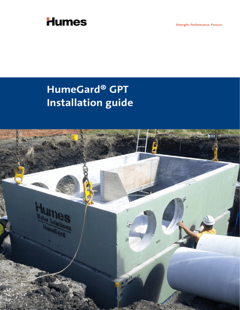
HumeGard® GPT
Installation guide
Purpose of this guide
This guide outlines the construction procedures and requirements for the
installation of the HumeGard® GPT. This document should be reviewed by
supervisory personnel prior to commencing any HumeGard® GPT installation.
The following information is of a general nature only and
It is the responsibility of the site owner and its
is not intended to be exhaustive or impose or imply any
contractors and consulting engineers to determine the
paticular requirements and should be read in conjunction
site’s suitability for construction, including access for
with project-specific documents including the contract,
plant, equipment and other issues.
project specifications and project drawings. This guide is
not a substitute for the project documentation.
Nothing in this guide is to be construed as a
representation, endorsement, promise, guarantee or
For typical installation requirements please refer to the
warranty whether expressed or implied.
Humes general assembly standard drawings or Humes
project-specific drawings. These are system assembly
Humes makes no representation or warranty, implied
drawings only and do not constitute and should not
or otherwise that, amongst others, the content of this
be construed as a site layout; the site layout should be
guide is free from errors or omissions or in relation
specified in project documents provided by the consulting
to the adequacy of the information contained in this
engineer who has been engaged by the asset owner.
guide and where appropriate you will seek verification
from an independent third party before relying on
Where the contents of this guide differ from project
any information in this guide. Humes is not liable or
specifications and drawings, supervisory personnel
responsible to any person for any use or reliance of any
should consult with a Humes engineer. In the event
information arising out of or in connection with this guide.
of any conflict between the information in this guide
and local legislative requirements, the legislative
requirements will take precedence.
Safety advice
The HumeGard® GPT must be installed in accordance
with all relevant health and safety requirements,
including the use of PPE and fall protection where
required.
Confined space entry
Installation of the unit may require confined space
entry. All equipment and training must comply to SHE
regulations. It is the responsibility of the contractor or
person/s entering the unit to proceed safely at all times.
Personal safety equipment
The contractor is responsible for the provision of
appropriate personal protection equipment including,
but not limited to safety boots, hard hat, reflective vest,
protective eyewear, gloves and fall protection equipment.
Make sure all equipment is used by trained and certified
personnel, and is checked for proper operation and safety
features prior to use.
Handling
The customer is responsible for unloading of the precast
components from the delivery vehicle. The customer
should familiarise themselves with the site conditions,
having regard for suitable space above and around the
excavation in order to install the unit safely. Particular
attention should be given to safety hazards such as
overhead power lines and other services in the vicinity
when considering positioning of cranes.
1. Excavation
Excavate to form a trench allowing adequate space to
accommodate the HumeGard® GPT. Shore or bench the
excavation if required.
If this is a retrofit installation, once excavation reaches
the level of the pipeline, carefully remove a number of
pipe lengths in order to provide an unobstructed opening
for further excavation. This practice will ensure pipe ends
are not damaged during lowering of the HumeGard® GPT
into the trench.
2. Bedding
It is important that the base of the excavation is
properly prepared with regard to line, level and degree
of compaction.
Humes recommends the use of 200 mm minimum depth
of compacted crushed rock as adequate bedding for the
HumeGard® GPT in most situations. It is important to
ensure that the bedding layer is well compacted and
levelled correctly so that the openings in the HumeGard®
GPT will accurately coincide with the inlet/outlet pipes
once fully installed.
The correct level of the bedding layer can be established
via the dimension depicted on the project drawing
(vertical distance from pipe invert to surface of
bedding layer).
2
HumeGard® GPT
HumeGard® GPT
3. Delivery
In most cases, the HumeGard® GPT will be delivered in
the following parts:
• a main chamber (encasing the boom, weir, baffles,
retention comb, internal slab). In the case of high
chamber mass (over 15 t) the main chamber may
consist of two parts (base and top section)
• a lid
• access covers and frames
• in the case of a two part chamber, loose stainless steel
retention comb components
A crane and lifting gear will be required to unload the
delivery vehicle. The crane must be of adequate capacity
to lift and lower the components into position. The
crane should be located to allow manoeuvrability of the
components into their correct position.
The main chamber and lid are designed for a maximum
sling angle of 60 degrees preferably using a differential
spreader beam connected via four lifting anchors on the
component. The size of the lifting anchors is shown on
the HumeGard® product drawing and must be advised to
the crane operator when booking the crane.
HumeGard® GPT
3
4. Placing the components
The chamber is supplied with inlet and outlet sides
clearly marked and the pipe ends should be cut to suit.
The position of the pipe centreline should be marked on
both the pipe end and the chamber surface to ensure
correct alignment relative to line and level through the
HumeGard® GPT.
It is important for the operation of the unit that the base
of the unit remains level and square horizontally after
positioning in the excavation. This should be carefully
checked particularly in the case of two part chambers
where dimensions of each part are measured before set
out and lowering into the excavation.
For two part chambers a sealed joint must be created
between the bottom and top sections. This can be
accomplished by placing either a mastic bead or a two
part epoxy resin (either will be supplied), along the
joint surface of the bottom component. The epoxy
resin should be approximately 80 mm wide and at least
6 mm thick.
5. Initial backfill
Once the main chamber is correctly positioned within
the excavation, backfill the sides of the excavation with
a suitable material to just below the inlet and outlet
openings. This will create a safe working platform to
enable the installation of the inlet and outlet pipes and
fitting of rubber connectors (if supplied).
4
HumeGard® GPT
HumeGard® GPT
6. Inspection of internal elements
For HumeGard® models that are supplied with some or
all of the stainless steel components separate, a Humes
representative should be consulted regarding their
correct fitting and adjustments.
7. Lid alignment and sealing
The lid must be joined to the main chamber using a
cement mortar layer approximately 10 mm in thickness
or suitable mastic sealant over the entire top surface
of all bearing walls. This will secure the lid to the main
chamber and ensure an even transfer of load stresses
down through the unit. The openings in the lid must be
positioned relative to the inlet and outlet sides of the
chamber as shown on the construction drawing supplied
with the large opening above the storage /retention area
on the inlet side.
8. Completing the installation
Once the lid is secure, if required, access chambers can be
constructed from the level of lid openings to the finished
surface level. Unless clearly stated otherwise, the supply
of these items is not included with the HumeGard®
components. The contractor is required to fit, cast-in
or bolt the access covers supplied to the top of access
chambers.
The remainder of the excavation can now be backfilled
and suitably compacted to the finished surface level.
HumeGard® GPT
5
Contact information
National sales 1300 361 601
humes.com.au
info@humes.com.au
Head Office
New South Wales
Tasmania
18 Little Cribb St
Grafton
Launceston
Milton QLD 4064
Ph: (02) 6644 7666
Ph: (03) 6335 6300
Ph: (07) 3364 2800
Fax: (02) 6644 7313
Fax: (03) 6335 6330
Fax: (07) 3364 2963
Newcastle
Ph: (02) 4032 6800
Queensland
South Australia
Fax: (02) 4032 6822
Adelaide
Ipswich/Brisbane
Sydney
Ph: (08) 8168 4544
Ph: (07) 3814 9000
Ph: (02) 9832 5555
Fax: (08) 8168 4549
Fax: (07) 3814 9014
Fax: (02) 9625 5200
Rockhampton
Tamworth
Ph: (07) 4924 7900
Ph: (02) 6763 7300
Fax: (07) 4924 7901
Fax: (02) 6763 7301
Western Australia
Gnangara
Ph: (08) 9302 8000
Townsville
Ph: (07) 4758 6000
Fax: (08) 9309 1625
Victoria
Perth
Fax: (07) 4758 6001
Echuca
Ph: (08) 9351 6999
Ph: (03) 5480 2371
Fax: (08) 9351 6977
Fax: (03) 5482 3090
Melbourne
Northern Territory
Ph: (03) 9360 3888
Fax: (03) 9360 3887
Darwin
Ph: (08) 8984 1600
Fax: (08) 8984 1614
National sales 1300 361 601
humes.com.au
info@humes.com.au
A Division of Holcim Australia
This brochure supersedes all previous literature on this subject. As the specifications and details contained in this publication may change please
check with Humes Customer Service for confirmation of current issue. This document is provided for information only. Users are advised to
make their own determination as to the suitability of this information or any Humes product for their own specific circumstances. We accept
no responsibility for any loss or damage resulting from any person acting on this information. Humes is a registered business name of Holcim
(Australia) Pty Ltd. HumeGard is a registered trademark; of Holcim. “Strength. Performance. Passion.” is a trademark of Holcim. HumeGard is
marketed, sold and manufactured by Humes Water Solutions under licence from Swinburne University of Technology.
© March 2015 Holcim (Australia) Pty Ltd ABN 87 099 732 297. All rights reserved. This guide or any part of it may not be reproduced without
prior written consent of Holcim.


