2/15.1/B/2
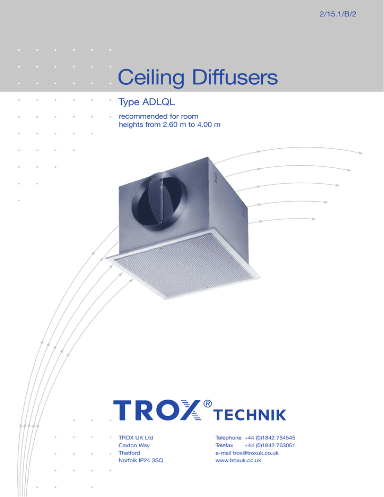
Ceiling Diffusers
Type ADLQL
recommended for room
heights from 2.60 m to 4.00 m
TROX UK Ltd
Caxton Way
Thetford
Norfolk IP24 3SQ
Telephone +44 (0)1842 754545
Telefax
+44 (0)1842 763051
e-mail trox@troxuk.co.uk
www.troxuk.co.uk
Contents · Description
Contents · Description _______________________________ 2
____ 3
Construction · Dimensions ________________________
__________________________________________
Materials
3
Directions of discharge · Blanking plates____________ 4
Nomenclature ________________________________________ 5
____ 5
Acoustic Data _____________________________________
Aerodynamic Data _________________________________ 9
Order Details ____________________________________ 10
ADLQL- . . . -H Construction
Type ADLQL ceiling diffusers are ideal for flush installation in
tiled ceilings. They are recommended for room heights
between 2.60 m and 4.00 m.
They are characterised by high induction, which results in
rapid decay of supply air velocity and temperature differential.
The recommended supply air temperature differential range
is 앐 10 K.
2
ADLQL- . . . -V Construction
Construction · Dimensions · Materials
Construction
Materials
Type ADLQL ceiling diffusers comprise a diffuser face fitted
with rear plenum box. The diffuser face has a border width of
either 11 mm for flush mounting into tiled ceilings or 30 mm
so that the border is surface mounted covering the ceiling
opening, for example in plaster ceilings.
The plenum box can be supplied with circular spigots top or
side entry. The side entry plenum box can also be provided
with internal acoustic lining and/or volume control damper
operable from the diffuser face (core removed).
The face border and neck section are fabricated from
aluminium extruded section.
The perforated face panel with return edges, side entry
plenum, top entry spigot plate and all internal baffles and
deflector plate are from galvanised sheet steel. The internal
acoustic lining is 12mm thick foam - Class 0.
The perforated face and border face are finished in RAL 9010
20% Gloss, colours available on request.
DA
Nom
D
Q1
Q2
K1
H1
K2
300
158
336
298
274
297
269
400
198
436
398
374
337
369
500
248
536
498
474
387
469
600
313
636
598
574
452
569
295*
148
–
295
271
297
266
595*
313
–
595
571
452
566
* Dimensions for diffuser to suit ‘T’ bar ceiling.
These dimensions apply to ADLQL-P-ZH and ADLQL-P-ZV only.
Type ADLQL (ADLQL-K-ZH-D-M shown)
Type ADLQL (ADLQL-P-ZH-D-M shown)
Type ADLQL (ADLQL-P-ZV shown)
88
Type ADLQL (ADLQL-K-ZV shown)
3
Directions of Discharge · Blanking plates
Blanking Plates
To provide various directions of discharge, blanking plates can
be supplied on request.
To mount these plates, the perforated sheet face must be
removed. The blanking plate is fixed to the plenum box using
self-tapping screws.
The fitting is by others on site.
Blanking Plates
Blanking plate
Directions of discharge
1 Blanking plate required per diffuser
2 Blanking plates required per diffuser
3 Blanking plates required per diffuser
4
Nomenclature · Acoustic Data
Nomenclature
in m: Distance from diffuser L = X + H1
in m/s: Time average air velocity at the wall at
distance L
˜ H1
in m/s: Time average air velocity between two diffusers
at distance H1 from ceiling
vø
in m/s: Air velocity in inlet spigot
ΔtZ
in K: Temperature difference between supply and
room air
ΔtL
in K: Difference between core and room temperature
at distance A/2 + H1 or L = X + H1
Δpt
in Pa: Total pressure drop
LWA in dB(A): A-weighted sound power level
LWNC
: NC rating of sound power level
LWNR
: LWNR = LWNC + 2
Δ L in dB/oct.: Relative level with respect to LWA
LW in dB/oct.: Octave band sound power level of regenerated
noise LW = LWA + Δ L
LpA, LpNC
: A-weighting and NC rating respectively of room
sound pressure level LpA 앒 LWA - 8 dB
LpNC 앒 LWNC - 8 dB
L
˜L
in l/s:
Volume flow per diffuser
in m3/h:
in l/s:
4
Volume flow for 4 way discharge diffuser
in m3/h:
For 3-; 2-; 1-; way discharge enter diagrams
using the following:
3 way: 4 = 1.33 ·
2 way: 4 = 2.0 ·
1 way: 4 = 4.0 ·
A
in m: Spacing between two diffusers
H1 in m: Distance between ceiling and occupied zone
Relative level and octave band centre frequency Type ADLQL- . . .-V
Relative level ΔL
1
Note: 1) Size 295 and size 595 performance is the same
as size 300 and size 600 respectively
vø in m/s
Vo
lum
ef
low
in l
/s
.
V. [m3/h] =
V [l/s] x 3.6
Size
5
1)
Octave band centre frequency in Hz
Acoustic Data
Insertion loss in dB/octave with internal lining
Insertion loss in dB/octave without internal lining
(includes end reflection loss)
(includes end reflection loss)
Octave band centre frequency in Hz
Octave band centre frequency in Hz
Size
63
125
250
500
1000
2000
4000
8000
Size
63
125
250
500
1000
2000
4000
8000
300
15
15
8
16
18
15
15
15
300
15
15
6
10
13
7
5
5
400
12
12
10
16
16
14
14
14
400
12
12
8
10
11
6
5
5
500
10
10
11
16
14
14
14
14
500
10
10
9
9
8
6
5
5
600
8
8
13
16
12
13
13
13
600
8
8
9
9
5
5
5
5
1)
LW
A
in
dB
(A)
Pressure drop Δpt in Pa
LW
A
Note: 1) Size 295 and size 595 performance is the same as size 300 and size 600 respectively
1)
in
dB
(A)
in
dB
(A)
Size
A
1)
Sound power level and pressure drop
Supply air type ADLQL- . . . -V
LW
in
dB
(A)
A
LW
Pressure drop Δpt in Pa
5
Sound power level and pressure drop
Supply air type ADLQL- . . . -V
Size
6
Sound power level and pressure drop
Supply air type ADLQL- . . . -V
Size
1)
Pressure drop Δpt in Pa
Size
3
4
Sound power level and pressure drop
Supply air type ADLQL- . . . -V
Pressure drop Δpt in Pa
2
Acoustic Data
Diagram 7:
Example
Data given:
Type ADLQL-. . .-H; Size 400
Volume flow with 4 way discharge
Damper angle
= 110 l/s
앒 30°
Required: Octave sound power level of regenerated
noise LW
Diagram 12:
Octave band
frequency
in Hz
63
125
250
500
LWA
in dB(A)
42
42
42
42
42
42
42
42
ΔL
in dB(A)
– 5
+ 3
– 3
– 7
– 3
– 9
– 18
– 28
LW
in dB
37
45
39
35
39
33
24
14
1000 2000 4000 8000
Sound power level and pressure drop
LWA = 46 dB(A)
Δpt = 38 Pa
vø = 3.6 m/s
Correction from table:
LWA = – 4 dB(A)
LWA = 46 – 4 = 42 dB(A)
6
Sound power level and pressure drop
Extract air type ADLQL- . . . -V
1)
LW
A
in
dB
(A)
Pressure drop Δpt in Pa
Size
Sound power level and pressure drop
Extract air type ADLQL- . . . -H
1)
LW
vø in m/s
Pressure drop Δpt in Pa
Relative level ΔL
Size
in
dB
(A)
8
Relative level and octave band centre
frequency type ADLQL- . . . -H
A
7
Octave band centre frequency in Hz
Note: 1) Size 295 and size 595 performance is the same as size 300 and size 600 respectively
7
Acoustic Data
Correction to diagrams 9 – 12
Size
300
400
500
600
LWA
LWNC
–6
–4
–2
0
9
11
Sound power level and pressure drop
Supply air type ADLQL- . . . -H
Pressure drop Δpt in Pa
dB
(A
)
in
W
A
-30°
)
(A
dB
LW
1)
Size
1)
Size
Volume flow
in l/s
Volume flow
12
Sound power level and pressure drop
Supply air type ADLQL- . . . -H
vø in m/s
1)
-90°
Pressure drop Δpt in Pa
Damper angle
)
(A
dB
.
V. [m3/h] =
V [l/s] x 3.6
Size
Volume flow
in
Sound power level and pressure drop
Supply air type ADLQL- . . . -H
in l/s
Note: 1) Size 295 and size 595 performance is the same as size 300 and size 600 respectively
A
LW
vø in m/s
1)
A
LW
in l/s
Size
Pressure drop Δpt in Pa
Damper angle -90° -60°
8
A
in
-60°
vø in m/s
vø in m/s
10
-90°
Damper angle
L
Pressure drop Δpt in Pa
Damper angle -90° -60° -30°
Sound power level and pressure drop
Supply air type ADLQL- . . . -H
Volume flow
in l/s
in
)
(A
dB
-60°
Aerodynamic Data
Example
Data given:
Type ADLQL; Size 300
Volume flow 2 way discharge
Spacing 1 between 2 diffusers
Distance between ceiling and occupied zone
= 40 l/s
A = 2.8 m
H1 = 1.2 m
Diagram 13:
Air velocity at the wall and temperature quotient
=2·
4
= 2 · 40 = 80 l/s
4
A/2
= 1.4 m
˜L
= 0.37 m/s
L
= 1.2 + 1.4 = 2.6 m
ΔtL/ΔtZ = 0.1
Diagram 14:
˜H1
= 0.17 m/s
13
Air velocity at the wall and temperature quotient
Air velocity between two diffusers
Effective outlet area
Size
400
500
600
0.0140
0.0254
0.0360
0.0600
Siz
e
1)
Aeff in
m2
300
14
Air velocity between two diffusers
H 1 in m
Size
1)
Distance L or A–2 in mm
Temperature quotient ΔtL/ΔtZ
˜ H1 in m/s
Note: 1) Size 295 and size 595 performance is the same as size 300 and size 600 respectively
9
Order Details
Order Code
ADLQL - K - ZH - D - M
/
300 x 158 x
/
0
/
0
/
P3
/
RAL 9010
/
20% Gloss
not used
K = 30 mm cover border
P = 11 mm flush border
Supply
ZH = horizontal spigot
ZV = vertical spigot
Finish
Reduced plenum size or blank
if standard diffuser size
EEI
EEE
EEEE
EEE
EE
EO
EEE
EEE
EEE
EPEE
Size (mm)
300
400
500
600
2952)
5952)
Type
Spigot size
M = spigot 1) damper or blank
D = Lining 1) or blank
Extract
AH = horizontal spigot
AV = vertical spigot
P3 Standard Finish
Powder-coated
to RAL 9010 20 %3)
P2 Powder-coated
to RAL 9006 25%3)
P4 Powder-coated
to RAL 9005 20%3)
P6 Other colours
to RAL ...
Order Code
BP - ADLQL
Design changes reserved · All rights reserved © TROX Ltd (11/2011)
Type
/ 300
All blanking plates are painted black (RAL 9005)
and supplied loose with screws for site fixing by others
Note:
1) Only available for horizontal spigot
2) Only available for flush border & layin “T” bar
3) % = Gloss level
Diffuser size
Specification Text
Order Example
Square ceiling diffuser for horizontal discharge, comprising face Make:
TROX
section and border which is either 30 or 11 mm wide. Screw
Type:
ADLQL-K-ZH-D-M/300x158/0/0/P3/RAL9010/20% Gloss
fixed perforated plate core with returned edges complete with
Accessories: BP-ADLQL/300
fitted baffle plate. Also with rear plenum box with internal baffle
with circular top or side entry spigots, optional items volume
control damper and internal acoustic lining.
Plenum box is firmly riveted to the diffuser face, 4 suspension
brackets provided to hang assembly from ceiling slab.
Materials:
Face border and neck section are fabricated from aluminium
extruded section. Perforated face panel with return edges, side
entry plenum, top entry spigot plate and all internal baffles and
deflector plate are manufactured from galvanised sheet steel.
The internal acoustic lining is 12mm thick foam - Class 0.
Finish
Perforated face and border face are finished in RAL 9010 20%
gloss. Plenum and top tray sections will be natural. Deflectors
and centre baffle plate disc will be painted matt black.
10


