I/O Box: BLG-BC2
Operation Manual for I/O Box BLG-IO-Pro1
Outline
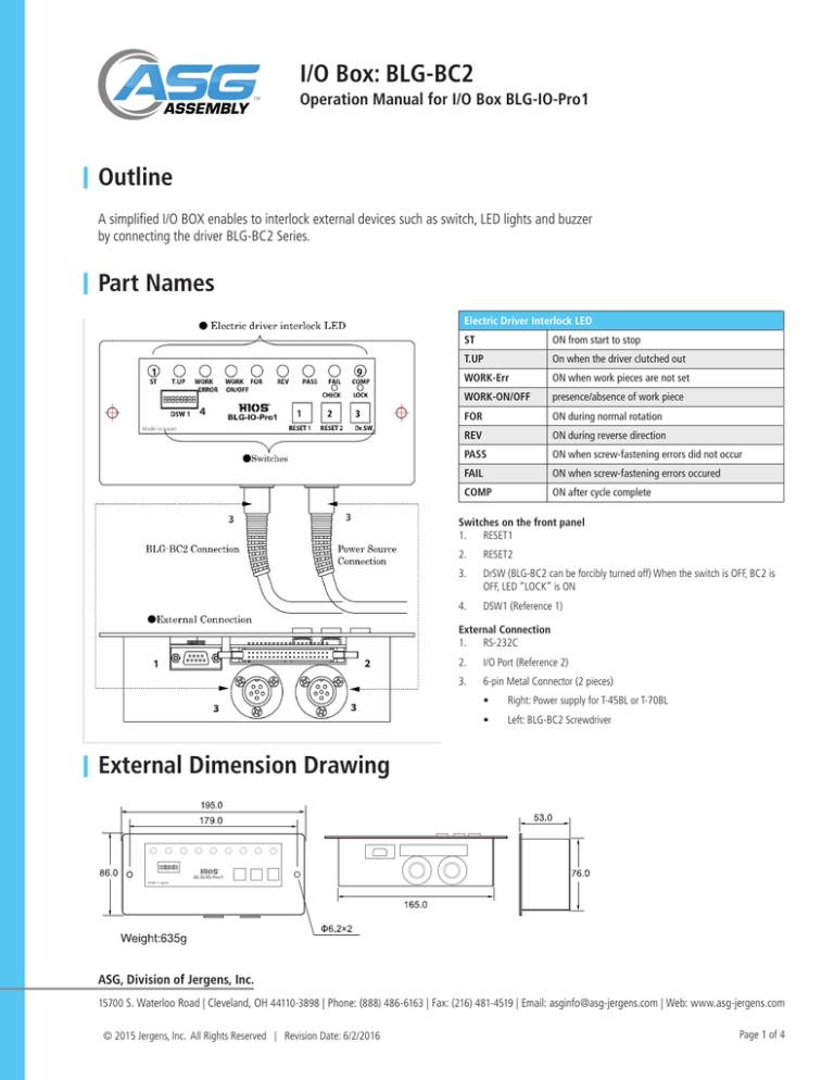
A simplified I/O BOX enables to interlock external devices such as switch, LED lights and buzzer
by connecting the driver BLG-BC2 Series.
Part Names
Electric Driver Interlock LED
ST
ON from start to stop
T.UP
On when the driver clutched out
WORK-Err
ON when work pieces are not set
WORK-ON/OFF
presence/absence of work piece
FOR
ON during normal rotation
REV
ON during reverse direction
PASS
ON when screw-fastening errors did not occur
FAIL
ON when screw-fastening errors occured
COMP
ON after cycle complete
Switches on the front panel
1. RESET1
2.
RESET2
3.
DrSW (BLG-BC2 can be forcibly turned off) When the switch is OFF, BC2 is
OFF, LED “LOCK” is ON
4.
DSW1 (Reference 1)
External Connection
1. RS-232C
2.
I/O Port (Reference 2)
3.
6-pin Metal Connector (2 pieces)
•
Right: Power supply for T-45BL or T-70BL
•
Left: BLG-BC2 Screwdriver
External Dimension Drawing
ASG, Division of Jergens, Inc.
15700 S. Waterloo Road | Cleveland, OH 44110-3898 | Phone: (888) 486-6163 | Fax: (216) 481-4519 | Email: asginfo@asg-jergens.com | Web: www.asg-jergens.com
© 2015 Jergens, Inc. All Rights Reserved | Revision Date: 6/2/2016
Page 1 of 4
I/O Box: BLG-BC2
Operation Manual for I/O Box BLG-IO-Pro1
DSW ON/OFF Operational Conditions (Reference Table 1)
NOTE: The default factory setting is “ON” for DSW1 #1 and #6.
DSW1#
Setting Name
1
Work-piece Set
2
Reset BC2 after a screwfastening error (Fail)
3
Set up mode buttons on BC2
4
Operation of screwdriver
after batch count complete
5
IO Pro1 Buzzer
6
Operation after an error (Fail)
7
NC
8
NC
Contents
ON
BC2 is operable regardless of presence
/absence of work-piece
OFF
BC2 is not operable when work-piece is absence.
ON: the count is returned to the value just before the
error occurred
OFF: reset, the count is returned to the default value.
All BC2 set up mode buttons are locked.
BC2 set up modes cannot be changed with
the buttons on the BC2.
LED “M” light on the BC2 is ON.
All BC2 set up mode buttons are unlocked.
BC2 set up modes can be changed with the
buttons on the BC2.
LED “M” light on the BC2 is OFF.
BC2 is not operable from batch count complete
until a new work-piece is set.
BC2 is operable after batch count complete.
Buzzer works upon PASS, Fail and cycle complete.
Buzzer does not work.
BC2 is still enabled upon Fail.
BC2 becomes disabled upon Fail.
Release (* Note: Same as DSW1-2)
Precaution
• DSW1 setting must be done when the I/O BOX is powered off.
• DSW1 #1
• should be “OFF” when an external work-piece set is used through the I/O Port.
• DSW1 #2
• When DSW1 #6 are “ON”
• BC2 is not disabled when the Fail LED is on. Press the RESET button on the front panel of I/O BOX to release.
• RESET buttons sequence
1. RESET1: For turning off the buzzer (BC2 is not enabled at this point.)
After confirming everything is ready to restart operation, press RESET2 button.
2. RESET2: BC2 becomes enabled.
• When DSW1 #5 or 6 are “ON”
When Fail LED turns on and buzzer sounds, BC2 becomes disabled. Press the RESET buttons to release.
• Order to push the RESET buttons
1. RESET1 -> For turning off the buzzer (BC2 is still disabled at this point.)
After confirming everything is ready to restart operation, press RESET2 button.
2. RESET2 -> BC2 becomes enabled.
ASG, Division of Jergens, Inc.
15700 S. Waterloo Road | Cleveland, OH 44110-3898 | Phone: (888) 486-6163 | Fax: (216) 481-4519 | Email: asginfo@asg-jergens.com | Web: www.asg-jergens.com
© 2015 Jergens, Inc. All Rights Reserved | Revision Date: 6/2/2016
Page 2 of 4
I/O Box: BLG-BC2
Operation Manual for I/O Box BLG-IO-Pro1
DSW ON/OFF Operational Conditions (Reference Table 1)
Precaution (Continued)
•
DSW1 #5
• should be “OFF” when an external work-piece set is used through the I/O Port.
Pin Configuration of the I/O Port Connector (Reference 2)
Pin Numbers and Names
GND
22, 23, 24, 25, 36, 37, 39
Low active input
(Operable on the input signal at Low level.)
26, 27
Workpiece Set
32, 33
RESET1
34, 35
RESET2
11
PASS/COMP (revolving lights, etc.)
12
T-UP/COMP (revolving lights, etc.)
13
Fail/COMP (revolving lights, etc.)
15
Buzzer (DSW1 interlock)
20
PASS
21
Fail
38
RXD
40
TXD
Open collector output
For connecting devices such as PC (RS232C).
Refer to “BC2 communication specifications”
How to Use the Low Active Interval Circuit
• The voltage should be less than 0.3V at LOW
• The voltage should be less than 30V for pull-up resister of an external voltage supply
ASG, Division of Jergens, Inc.
15700 S. Waterloo Road | Cleveland, OH 44110-3898 | Phone: (888) 486-6163 | Fax: (216) 481-4519 | Email: asginfo@asg-jergens.com | Web: www.asg-jergens.com
© 2015 Jergens, Inc. All Rights Reserved | Revision Date: 6/2/2016
Page 3 of 4
I/O Box: BLG-BC2
Operation Manual for I/O Box BLG-IO-Pro1
Pin Configuration of the I/O Port Connector (Reference 2) (Continued)
The reference structural outline when an external buzzer is installed and interlocks with the I/O BOX buzzer is externally installed
(External power supply is needed for the external buzzer.)
Other Specifications
• Consumption current 30V/40mA (Please use the HIOS power supply T-BL series dedicated to
HIOS electric screwdriver)
• Open collector output (max. 40V/40mA)
• Items included in the package
• BLG-IO-Pro1: 1 unit
• 6-pin driver cord 2m: 1pc
• 40-pin connector (250mm) : 1pc
• BLG-IO -Pro1 Operation Manual: 1copy
• NOTE: The BLG-BC2 I/O Cable is optional and not included in the package.
ASG, Division of Jergens, Inc.
15700 S. Waterloo Road | Cleveland, OH 44110-3898 | Phone: (888) 486-6163 | Fax: (216) 481-4519 | Email: asginfo@asg-jergens.com | Web: www.asg-jergens.com
© 2015 Jergens, Inc. All Rights Reserved | Revision Date: 6/2/2016
Page 4 of 4


