IXAN0022
Capitalizing on the Advantages of ISOPLUS Products
Introduction
IXYS Corporation offers unique power packages
with internal isolation, and performance and
reliability advantages. The IXYS isolated packages
include ISOPLUS220TM, ISOPLUS247TM, ISOPLUS
i4-PAC TM, ISOPLUS264 TM as well as the new
ISOPLUS-DIL TM modules. The ISOPLUS
advantages relative to the standard power packages
include:
• Better electrical isolation
• Larger and multiple die
• Multiple circuit configurations
• Lower thermal resistance
• Higher reliability
• UL recognition has been granted to the
ISOPLUS220, ISOLPUS247 and ISOPLUS
i4-PAC
• Higher component density
• Easy clip assembly
This article will describe and quantify the
ISOPLUS advantages and focus on mounting
techniques and materials that optimize the ISOPLUS
performance and capitalize on their inherent
advantages. The focus will be on the ISOPLUS220
and ISOPLUS247 examples, but quantitative tools
will be provided for the designer to apply the
approach to all ISOPLUS packages.
Electrical Isolation
Electrical isolation between the power die and
heatsink is provided by Direct-Copper-Bonded
(DCB) ceramic substrates, which are integrated into
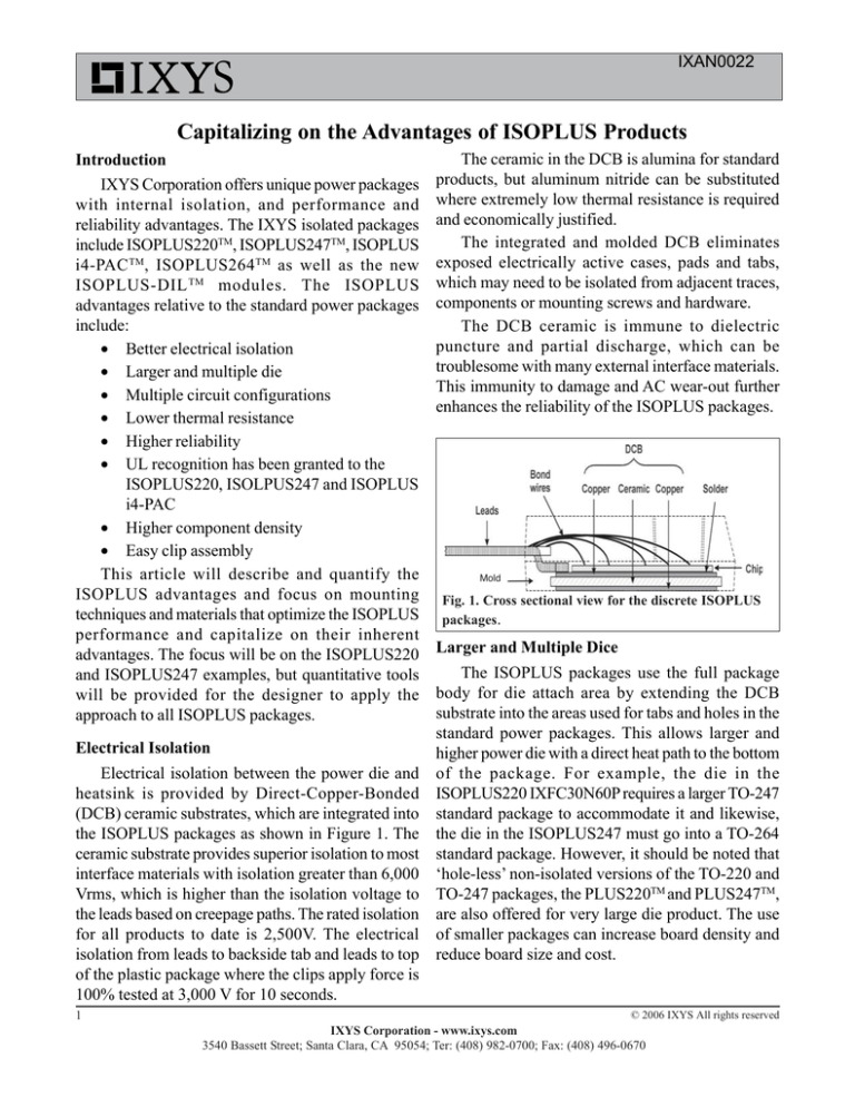
the ISOPLUS packages as shown in Figure 1. The
ceramic substrate provides superior isolation to most
interface materials with isolation greater than 6,000
Vrms, which is higher than the isolation voltage to
the leads based on creepage paths. The rated isolation
for all products to date is 2,500V. The electrical
isolation from leads to backside tab and leads to top
of the plastic package where the clips apply force is
100% tested at 3,000 V for 10 seconds.
1
The ceramic in the DCB is alumina for standard
products, but aluminum nitride can be substituted
where extremely low thermal resistance is required
and economically justified.
The integrated and molded DCB eliminates
exposed electrically active cases, pads and tabs,
which may need to be isolated from adjacent traces,
components or mounting screws and hardware.
The DCB ceramic is immune to dielectric
puncture and partial discharge, which can be
troublesome with many external interface materials.
This immunity to damage and AC wear-out further
enhances the reliability of the ISOPLUS packages.
Mold
Fig. 1. Cross sectional view for the discrete ISOPLUS
packages.
Larger and Multiple Dice
The ISOPLUS packages use the full package
body for die attach area by extending the DCB
substrate into the areas used for tabs and holes in the
standard power packages. This allows larger and
higher power die with a direct heat path to the bottom
of the package. For example, the die in the
ISOPLUS220 IXFC30N60P requires a larger TO-247
standard package to accommodate it and likewise,
the die in the ISOPLUS247 must go into a TO-264
standard package. However, it should be noted that
‘hole-less’ non-isolated versions of the TO-220 and
TO-247 packages, the PLUS220TM and PLUS247TM,
are also offered for very large die product. The use
of smaller packages can increase board density and
reduce board size and cost.
© 2006 IXYS All rights reserved
IXYS Corporation - www.ixys.com
3540 Bassett Street; Santa Clara, CA 95054; Ter: (408) 982-0700; Fax: (408) 496-0670
IXAN0022
The ISOPLUS packages provide more internal
space for multiple die and the DCB provides a natural
technique for isolated metallization for multiple die
attach pads and interconnecting traces. The multichip discrete power packages like the ISOPLUS220
and ISOPLUS247 led to the larger 4-lead and 5-lead
ISOPLUS264 and
ISOPLUS i4-PAC as
well as the ISOPLUS
DIL modules, shown in
the illustration with 5
power leads and 12
signal leads. Additional
circuit configurations
are now available in ISOPLUS package options.
Examples include AC switches, buck and boost
configurations with either MOSFETs or IGBTs,
common anode or series connected diodes, halfbridge and new 3-phase, Trench MOSFET bridges
in the ISOPLUS-DIL package.
Clip Assembly
The ISOPLUS packages eliminate the mounting
hole to allow a large DCB substrate, which improves
isolation, reduces thermal resistance and allows a
larger internal die area. The elimination of the
mounting hole has become another advantage of the
ISOPLUS package, because it allows the use of
30
25
Force - Pounds
KU4-499
20
15
KU4-498
10
5
0
0
20
40
60
80
100
120
140
160
180
Displacement - mils
Fig. 2: Clamping force for the Kunze clips KU4-498
and KU4-499.
component clips without special tab or hole isolation,
and excessive isolation spacing.
Component clips can simplify assembly by
eliminating mounting screws with their associated
hardware like screws, threaded holes, washers and
insulators. Furthermore, clips do not require
controlled torque and clamping force as clips are predesigned for a given clamping force for a given
package thickness..
Interface materials like silicone grease and thermal
pads are often use with lower force clamps, and such
materials and clamps can be used with the ISOPLUS
packages. New high performance phase change
materials often require much higher clamping forces
to achieve the lowest possible thermal resistance.
Kunze Folien offers a number of high force clamps
for power packages.
• The Power Clip KU4-498 is an excellent clip
for the ISOPLUS220 or ISOPLUS247 providing
clamping force of 23 lbs, or 90 lbs per square inch
for these two packages.
• The Power Clip KU4-499 is an excellent clip
for the ISOPLUS247, ISOPLUS264 and ISOPLUS
i4-PAC providing for providing a mounting force of
29 lbs.for these packages.
• The KU4-495 is a dual clip for mounting
either two ISOPLUS220 or ISOPLUS packages sideby-side.
The clamping force for the KU4-498 and KU4499 power clips is shown in Figure 2 and is a function
of clip displacement.. These clips are available in
Multi Transistor Clip configurations, which can
further simplify assembly, and multi transistor clips
are easier to use with the ISOPLUS packages where
all isolation is internal. Table 2 provides a Cross
Reference between Kunze Power Clips and Power
Semiconductor packages, both ISOPLUS and
standard packages.
Thermal Resistance
The primary advantage of the ISOPLUS packages
is that their exceptionally low thermal resistance
© 2006 IXYS All rights reserved
IXYS Corporation - www.ixys.com
3540 Bassett Street; Santa Clara, CA 95054; Tel: (408) 982-0700; Fax: (408) 496-0670
2
IXAN0022
Table 1: Thermal Resistance Junction-to-Case Comparison of
ISOPLUS Package Types to Standard Package Types
Package Type
ISOPLUS220
PLUS220*
ISOPLUS247
PLUS247*
Part Number
Die Size (mm)
IXFC30N60P
8.9X7.4
IXFV30N60P
8.9X7.4
IFR64N60P
14.2x10.6
IXFX64N60P
14.2x10.6
Clip Type
Interface-Conductive
KU4-498
KU-ALF 5
KU4-498
(NA)
KU4-499
KU-ALF 5
KU4-499
(NA)
Interface-Isolated
R(th)JC (max)
(NA)
0.75 K/W
KU-KG 2.5
0.25 K/W
(NA)
0.35 K/W
KU-KG 2.5
0.12 K/W
R(th)CS(max)
0.07 K/W
1.74 K/W
0.05 K/W
0.93 K/W
R(th)JS (max)
0.82 K/W
1.99 K/W
0.40 K/W
1.05 K/W
* ‘Hole-less’ versions of the ISOPLUS220 and ISOPLUS247 packages respectively.
material, like the KU-ALF 5. Its thermal resistance
is plotted versus applied pressure in Figure 3. Kunze
Folien also provides state-of-the-art isolated, phase
change materials, like KU-KG 2.5 for standard power
packages. However, their thermal resistance per area
can be more than ten times greater as evidenced in
Figure 4.
The product examples shown in Table 1 are
The ISOPLUS packages are already isolated
allowing direct mounting to heatsinks. However, the representative of the improvements that can be
use of silicone grease, thermal pads, or one of the achieved with in the ISOPLUS220 and ISOPLUS247
high performance conductive phase-change materials packages with larger die products and with the
be used to reduce contact resistance. Kunze Folien recommended interface materials shown above.
offers state-of-the-art conductive phase change
(R(th)js) from device junction to case, for power
devices requiring isolation from the heatsink. The
ISOPLUS packages can provide 10 to 50 percent
lower R(th)js than standard packages with the same
die and external isolation. The greatest thermal
advantages occur with larger die products, which are
the focus of the ISOPLUS products.
0.14
Thermal Resistance - K/W
Thermal Resistance - K/W
0.025
0.020
0.015
0.010
0.005
0.12
0.11
0.10
0.09
0.08
0.000
0
10
20
30
40
50
60
70
80
Clamp Pressure - PSI
Fig. 3: KU-ALF 5 Thermal Resistance per Square
Inch vs. Clamp Pressure.
3
0.13
90
0
10
20
30
40
50
60
70
80
90
Clamp Pressure - PSI
Fig. 4: KU-KG 2.5 Thermal Resistance per Square
Inch vs. Clamp Pressure.
© 2006 IXYS All rights reserved
IXYS Corporation - www.ixys.com
3540 Bassett Street; Santa Clara, CA 95054; Ter: (408) 982-0700; Fax: (408) 496-0670
IXAN0022
The above comparisons are based on ISOPLUS
products with DCB alumina substrates. If the DCB
alumina is replaced by DCB aluminum nitride, the
thermal resistance can be reduced significantly
because the thermal conductivity of aluminum
nitride is 7 times higher than alumina.
Reliability
Power Semiconductor products are always
limited by the Coefficient of Thermal Expansion
(CTE) mismatch between the die and copper case.
The CTE mismatch limits both die size, load cycle
capability and temperature cycling reliability. In the
ISOPLUS package, the die is attached to the DCB
ceramic substrate, and CTE mismatch between the
die and substrate is much less than between die and
copper. This increases the ISOPLUS package
reliability in temperature cycling, and allows the
package to withstand larger temperature excursions
and number of cycles without damage. The DCB
substrate also allows the use of larger power die than
can be used directly on copper.
Higher Component Density
A secondary advantage of the ISOPLUS packages
is that they provide higher board densities.
The ISOPLUS packages accommodates larger die
in a smaller package outline, and the isolated packages
can be placed closer together. In some cases, groups
of multiple isolated packages can clamped by single
multiple fingered clips. Semicustom, cost effective
configurations can be developd for qualified
opportunites.
Table 2: Package Cross Reference for Kunze Power Clips
Package Type
Kunze Clip Model*
TO-3P
KU3-392, 3-396/24, 3-397, 3-399, 4-440/3.1, 4-440/4.0,
4-441, 4-443, 4-450, 4-453, 4-490
TO-3P Double
KU4-445
TO-220
KU3-381, 3-386, 3-387, 3-388, 3-389, 3-399, 4-440/3.1,
4-440/4.0, 4-441, 4-443, 4-450, 4-453, 4-490
TO-220 Double
KU4-430, 4-445, 4-495 Gull Wing Clip
TO-220 Multiple
Transistors
KU4-498/X (X = number of transistors)
ISOPLUS220
KU4-498/X (X = number of transistors)
TO-247
KU3-392, 3-396, 3-397
TO-247 Double
KU4-495 Gull Wing Clip
TO-247 Multiple
Transistors
KU4-499/X (X = number of transistors)
ISOPLUS247
KU4-499/X (X = number of transistors)
TO-247AD
KU3-393
ISOPLUS DIL
KU4-501
ISOPLUS i4-PAC KU3-393, 3-395
TO-264 Multiple
Transistor
KU4-499/X (X = number of transistors)
ISOPLUS264
KU4-499/X (X = number of transistors)
* Go to <www.heatmanagement.com> for clip and interface material data sheets.
© 2006 IXYS All rights reserved
IXYS Corporation - www.ixys.com
3540 Bassett Street; Santa Clara, CA 95054; Tel: (408) 982-0700; Fax: (408) 496-0670
4


