International Journal of Science, Engineering and Technology Research (IJSETR), Volume 4, Issue 8, August-2015
Time Delay Estimate Based Real Time Audio Signal Source
Localization Technique for Intelligent Robotic Applications
V. RASAGNYA, Student,
Aurora's Technological and Research Institution,
Hyderabad, Telangana.
Abstract— The present day robots can do defined jobs with
predefined movements. These are very effectively used in
industrial production lines to increase the throughput and
reliability of the product design. The next generation robots
are expected to come with intelligence to serve the industrial
and domestic needs. The main challenge today is to build
intelligence in robots to dynamically move for providing
appropriate service. The concept of identifying the sound
source direction would be very much useful for robots, so that
they can move towards the sound origin direction and provide
appropriate service. Adding to this a small obstacle detection
or range detection system can stop the robot at a predefined
distance from the sound origin. This algorithm with suitable
modification is also useful in military applications. This system
will be modeled and will be implemented with VHDL. The
algorithm will be synthesized to Xilinx FPGA. The complete
setup will be demonstrated with the Block RAM’s. The system
employs Block RAM’s with different audio samples and
calculates the direction of the sound source using TDOA
(time-delay of arrivals). All the functions for the sound source
localization are implemented with the use of algorithms for
acoustic signal capturing, cross correlation, short-term energy
and azimuth computation.
P. MAMATHA, Asst. Professor,
Aurora's Technological and Research Institution,
Hyderabad, Telangana.
processing setup.
By using the olden camera system the number of cameras
that would capture the image or thief will be hardly one or
two. So in order to improve the performance of that camera
system ―sensors‖ will be used. So many types of sensing
devices are there like voice sensor, light sensor etc.
Modelsim Xilinx edition (MXE) tool will be used for
simulation and functional verification. Xilinx Synthesis
technology (XST) will be used for FPGA synthesis. Timing
analysis will be carried out to predict the maximum
achievable clock speeds for chosen Xilinx Spartan 3E FPGA
device. The RTL code for the design will be done using
VHDL. A test bench will be written to verify the functional
correctness of the code.
II. BLOCK DIGARAM AND IMPLEMENTATION
A. Block diagram
Index Terms— Audio Source Localization, Xilinx, Modelsim,
Spartan 3E, FPGA.
I. INTRODUCTION
Today security systems are playing vital role in war field,
home and industrial security. In case of any theft or robbery
the police people depend mostly on recorded video/still
camera information. In case of military, spy operations or
surveillance spy robots are used however in most of the cases;
the number of cameras which can capture the thief’s
video/image will be very few. This is because the present
camera system will install the cameras to look in one specific
angle only. If the modern camera systems are equipped with
intelligence to move in various directions based on some
sensor processing then it would give better video/image of
the thief from different directions at a time. This technology
also can reduce the number of cameras required to be
installed to cover a specific area.
In major thief/robbery situations the premises will be very
calm and any small sounds can be easily captured by typical
microphones. Since the sound travels with low velocity (330
m/s) if we keep three microphones at a distance of few tens of
centimeters then the three sensors outputs will be with some
delay. This delay directly corresponds to the angle of sound
source. Based on this fact we can build direction estimation
systems with three microphones and FPGA based signal
ISSN: 2278 – 7798
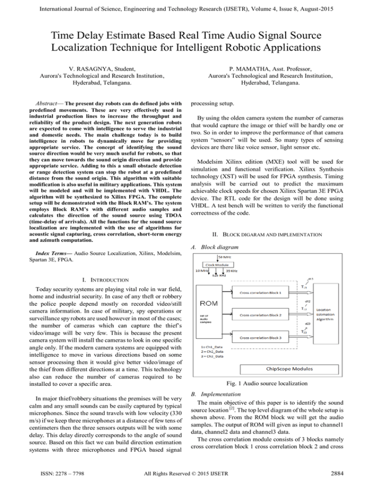
Fig. 1 Audio source localization
B. Implementation
The main objective of this paper is to identify the sound
source location [2]. The top level diagram of the whole setup is
shown above. From the ROM block we will get the audio
samples. The output of ROM will given as input to channel1
data, channel2 data and channel3 data.
The cross correlation module consists of 3 blocks namely
cross correlation block 1 cross correlation block 2 and cross
All Rights Reserved © 2015 IJSETR
2884
International Journal of Science, Engineering and Technology Research (IJSETR), Volume 4, Issue 8, August-2015
correlation block 3. The channel1 data and channel 3 data
would be fed to cross correlation block 1, channel1 data and
channel2 data would be fed to cross correlation block 2 and
channel2 data and channel3 data would be fed to cross
correlation block 3. The cross correlation operation for the
received signals would be done in their respective blocks.
The output from the cross correlation blocks would be a time
delayed signal. These time delayed signals T13, T12 and T23.
Location estimation block inputs are T 13, T12 and T23. Fine
difference between inputs cross correlation and generates
signal’s which is used to find coordinates using the cost
function and grid search method. Below it is explained in
detail.
The location estimation algorithm will not take time
difference (T12, T13 and T23) instead takes d12, d13, d23.
In this algorithm we are finding
d1= ((x (i)-x1) ^2+(y (j)-y1) ^2) ^.5
d2= ((x (i)-x2) ^2+(y (j)-y2) ^2) ^.5
d3= ((x (i)-x3) ^2+(y (j)-y3) ^2) ^.5
storing the predefined values as there is the problem with
balanced microphones.
Sample averaging: If we take the average of signals to find
the cross correlation, we overcome noise because noise will
have zero mean i.e. when we take average zero mean effect of
the noise is reduced.
Inside the FPGA we use random signal generator (1000
sound samples) that are kept in ROM and synthesized on to
FPGA. A block naming as position to delay mapper gives the
coordinates (x, y) where the target is there, based on that
basically delays required in ch1, ch2, ch3 will be produced.
In reality, the output signal from the microphones differs
only in delay (there is no mismatch in amplitude or phase)
exactly the similar kind of signal is generated and fed into the
256 point cross correlation block.
We find out cross correlation by shift and multiply and not
by FFT as it is a tedious method.
III. HARDWARE
A. Spartan 3E Board
Fig. 2 Location estimation grid
We find the difference between d1 and d2 we get the
correspondingd2-d1,
Dis12=t12*constant
(constant=velocity *1/fs=(330m/s)*0.256msec(in Q11
format) (since fs=39062.5)
(t12 we get it from cross correlation index, where as d1-d2
we get by assuming the coordinates of sound source in a
specific grid)
Fig. 3 Spartan 3E FPGA board
B. FPGA Structure
Diff12=(d2-d1) –dis12
Similarly Diff23=(d2-d3) – dis23, Diff13=(d1-d3) – dis13
Costfunction=(diff12*diff12)+(diff23*diff23)
+( diff13*diff13)
Where the cost function is minimum the corresponding x
and y coordinates results the true sound source coordinates.
By using real microphones we can capture real sound
signal by using pc speakers or cell phones. Figure 2 shows the
grid which is used in finding location of the source. Sound
source from different places are generated accordingly to x
and y coordinates of the sound source. Second method is of
Fig. 4 FPGA structure
2885
ISSN: 2278 – 7798
All Rights Reserved © 2015 IJSETR
International Journal of Science, Engineering and Technology Research (IJSETR), Volume 4, Issue 8, August-2015
IV. SIMULATION RESULTS
VI. CONCLUSION
In this work we presented an audio signal source
localization technique that is able to determine the
coordinates of sound source. The design is novel, cheap and
simple. Active Strengths of this implementation are the
simplicity of the design and the low cost, while a weakness is
the exact coordinates can’t be found but the approximate
result can be found and this device works in noise free
environment. Application of this device is possible for
security purpose.
REFERENCES
[1]
[2]
[3]
Fig. 5 Simulation Results
[4]
Channel1 data, Channel2 data and Channel3 data are the
data that is generated by ROM block. After processing of
cross correlation for channel1 and channel2 resultant
maximum peak and maximum index is updated in maximum
correlation value12 and maximum correlation index12
respectively. Similarly other two channels will be also
updated respectively in maximum correlation value23,
maximum correlation value31 and maximum correlation
index23, maximum correlation index31. Signal correlation
out value12, Signal correlation out value23 and Signal
correlation out value31 these shows correlation operation
(i.e. magnitude) output for all the samples. Signal
correlation out index12, Signal correlation out index23 and
Signal correlation out index31 these represents relative time
delay (i.e. T12, T23, and T31) for all the samples. Correlation
output clock will be active high when cross correlation
operation has been completed Delay12, delay23 and delay13
will be updated from the index values all other signals are
explained in the top module wave form explanation.
[5]
Acoustic Localization based on FPGA Ivan Aleksi, Željko Hocenski,
Petar Horvat, IEEE 2010.
D. Nguyen, P. Arabi, A. Sheikholeslami, "Real-time Sound Localisation
Using Field Programmable Gate Arrays", In Proc. of IEEE Int. Conf. on
Acoustic, Speech & Signal.
Xilinx, "Spartan-3E Starter Kit Board User Guide", UG230 (v1.0),
March 9, 2006.
M.R. Azimi-Sadjadi, G. Kiss, B. Feher, S. Srinivasan, A Ledeczi,
"Acoustic Source Localization with High Performance Sensor Nodes", In
Proc. of SPIE Int. society for optical engineering, vol. 6562, p. 65620,
USA, 2007.
A. Li, S. Wang, and F. Hu, ―DOA estimation of coherent signal using
MUSIC algorithm with nonuniform sampling,‖ 2008 Congress on Image
and Signal Processing, pp. 431–435, 2008.
Authors:
V.RASAGNYA pursuing M.Tech in VLSI (ECE
Department) at Aurora's Technological and Research
Institution, Hyderabad, Telangana.
P.MAMATHA working as an Assistant Professor at
Aurora's Technological and Research Institution,
Hyderabad, Telangana. She has an M.Tech degree in VLSI
System Design.
V. TABLE
Logic utilization
used
available
utilization
Number of slice
flip flops
Number of 4 input
LUT’s
Number
of
occupied slices
Number of bonded
IOB’s
Number of block
RAM’s
1,319
9,312
14%
1,521
9,312
16%
1,957
4,656
42%
66
232
28%
10
20
50%
Table 1 Device utilization summary
ISSN: 2278 – 7798
All Rights Reserved © 2015 IJSETR
2886


