Cooper Power Systems Success Story Article
advertisement

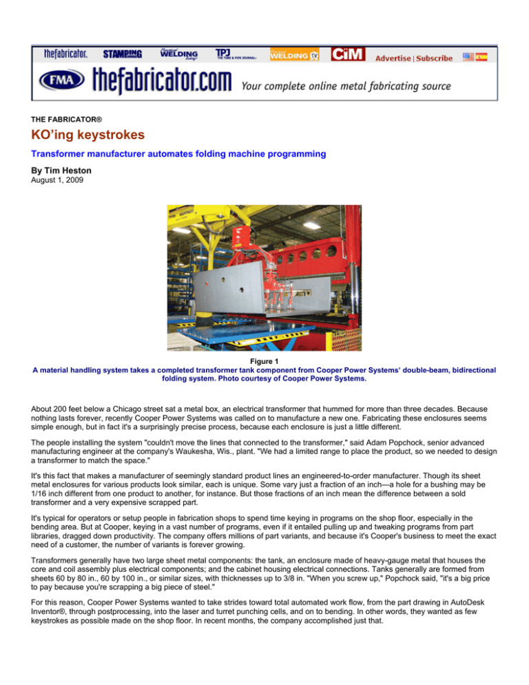
THE FABRICATOR® KO’ing keystrokes Transformer manufacturer automates folding machine programming By Tim Heston August 1, 2009 Figure 1 A material handling system takes a completed transformer tank component from Cooper Power Systems’ double-beam, bidirectional folding system. Photo courtesy of Cooper Power Systems. About 200 feet below a Chicago street sat a metal box, an electrical transformer that hummed for more than three decades. Because nothing lasts forever, recently Cooper Power Systems was called on to manufacture a new one. Fabricating these enclosures seems simple enough, but in fact it's a surprisingly precise process, because each enclosure is just a little different. The people installing the system "couldn't move the lines that connected to the transformer," said Adam Popchock, senior advanced manufacturing engineer at the company's Waukesha, Wis., plant. "We had a limited range to place the product, so we needed to design a transformer to match the space." It's this fact that makes a manufacturer of seemingly standard product lines an engineered-to-order manufacturer. Though its sheet metal enclosures for various products look similar, each is unique. Some vary just a fraction of an inch—a hole for a bushing may be 1/16 inch different from one product to another, for instance. But those fractions of an inch mean the difference between a sold transformer and a very expensive scrapped part. It's typical for operators or setup people in fabrication shops to spend time keying in programs on the shop floor, especially in the bending area. But at Cooper, keying in a vast number of programs, even if it entailed pulling up and tweaking programs from part libraries, dragged down productivity. The company offers millions of part variants, and because it's Cooper's business to meet the exact need of a customer, the number of variants is forever growing. Transformers generally have two large sheet metal components: the tank, an enclosure made of heavy-gauge metal that houses the core and coil assembly plus electrical components; and the cabinet housing electrical connections. Tanks generally are formed from sheets 60 by 80 in., 60 by 100 in., or similar sizes, with thicknesses up to 3/8 in. "When you screw up," Popchock said, "it's a big price to pay because you're scrapping a big piece of steel." For this reason, Cooper Power Systems wanted to take strides toward total automated work flow, from the part drawing in AutoDesk Inventor®, through postprocessing, into the laser and turret punching cells, and on to bending. In other words, they wanted as few keystrokes as possible made on the shop floor. In recent months, the company accomplished just that. A Standard Folding Language Most tank and cabinet enclosures are processed through a series of lasers or turret punch presses, on to press brakes or folding systems, then welding, finishing, painting, and assembly. It looks like typical part flow until you consider what the operators are doing, particularly at the double-beam, bidirectional folding machine: No typing and few, if any, mouse clicks are required to form large parts. There's no designated programmer anywhere, in fact. Cooper not only took folder programming off the shop floor, but also eliminated the need for anyone to program the folding machine at all. Working with software firm Logic Design Corp. (LDC), Pewaukee, Wis., Cooper engineers employ what's called Standard Folding Language™, or SFL, code developed by LDC to serve as a kind of conduit between the design file and the machine control. It takes AutoDesk Inventor (IPT) files, unfolds and sizes them based on the machine's bending tolerance, and then sends that program to a server location. This occurs about four or five hours before the part reaches the double-beam folding machine, which uses a material handling system to move parts to and from the folding area (see Figures 1-4). The SFL file is then downloaded and automatically translated into code the folding machine can understand. Popchock conceded that it took "only 30 seconds in some cases to make a folding program [at the machine]. But the operator had to visually review it quickly. That's lost time. We wanted our operators to be forming parts, not programming the machine." The technology Cooper employs is significant for two reasons. One, it totally automates bend programming for the folding machine. Cooper has no need for a dedicated folding machine programmer on or off the shop floor. Second, SFL is designed to be machine and brand-neutral, so it can be used for a folding machine, panel bender, press brake, or other bending technology. SFL code also is a subset of LDC's Global Edge® software designed to work with the gamut of fabrication technologies. The software unfolds 3-D CAD files, creates flat DXF files, inserts specific weld marks and other elements not included in the original IPT file, and places the DXFs in a server directory for SigmaNEST® software to take and develop a nest for the laser cutting system. Figure 2 Cooper’s folding system folds up the first large flange of a transformer tank. Photo courtesy of Cooper Power Systems. Cooper Power Systems has not only taken folder programming off the shop floor, but also eliminated the need for anyone to program the folding machine at all. Completely Automating Folder Programming Lars Hedman, LDC sales manager, pointed out two required elements of automated bend programming at Cooper. The first involved working with bending machine suppliers to develop a converter that changes generic SFL into machine-specific code, circumventing a folding machine's bending template to develop programs. Such a converter, which was developed for Cooper's dual-beam folding machine, really is the keystone to the whole operation. Without it, programming couldn't become completely automated because an operator still would need to key in commands at the machine. The second hurdle was to ensure the SFL considered the specific parameters of Cooper's dual-beam folding machine. The software stores all the tooling and other parameters that determine a part's clearance. As Hedman explained, the software initially draws information from the original 3-D CAD file and analyzes it to ensure the parts can indeed be cut and bent with the machines available on the floor. For the folding system the software conducts what's called an X-Y-Z analysis to ensure the part will fit within the machine's space limitations. In doing so, it checks to see if flanges have sufficient clearance as it determines the best folding sequence. Because the software conducts the manufacturability analysis upfront, it can reject the program immediately if it can't be made, before anything hits the shop floor. Of course, all this is easier said than done. As Eric Hedman, LDC's chief technical officer, explained, the software draws from machinespecific profile information. Cooper uses a bidirectional folding system. When the software performs a collision check, it knows when and where the machine's cross beam rises and lowers to position a part for folding. "So to avoid collision, the highest flange length [for up-bends] has to be less than this maximum rise" of the cross beam, Eric said. When bending down, it knows how far off the floor the actual bend occurs, which sets the flange-length limits on down-bends. "And it continues to get more complicated beyond that," he said, as algorithms determine multiple flange-length limits, as well as other parameters, for any series of up and down bends that might occur. Springback compensation was another hurdle. The software draws from tables developed at Cooper after testing various gauges and material types at different angles. From these "we'll adjust the part in the original 3-D drawing before we do a flat-pattern layout to match the bend radius required," Eric explained. After this, the software creates a new flat pattern adjusted to account for the new bend radii, and only then is the file sent to the floor for cutting and bending. After much preparation and back-and-forth between Cooper and its machine and software suppliers, the company finally was able to minimize those shop floor keystrokes. Today at Cooper an order releases from the enterprise resource planning (ERP) system, which specifies part numbers and the quantities for each job. From here Global Edge software takes the 3-D part drawings from AutoCAD Inventor and pulls them down to the work queue. Once the part files are in the work queue, the software determines which will be routed to which machines, and makes changes to allow for bend tolerances on specific equipment and tooling. Then it unfolds the 3-D CAD model, creates a flat DXF, and, as described previously, prepares it for the nesting software. Meanwhile the folding programs are automatically generated and are ready for the double-beam folding machine operator to pull them from the server and process the part. Figure 3 The folding machine completes the transformer tank section. Photo courtesy of Cooper Power Systems. Next Steps Besides automated programming, the company eliminated duplicate drawings and revisions, previously somewhat unorganized, and simplified part numbering at the shop floor level. Instead of looking up a 22-digit part number, workers need only read a short identifier showing the part number and revision: as a hypothetical example, 123-002 would be the second revision of part no. 123. (This also sped the cutting operation because the laser etches part numbers onto the blanks; a 22-character part number takes some time to etch.) To work toward automated work flow, as Lars explained, it makes sense for companies to start at the most downstream bottleneck— that is, machine programming—and work backward. Cooper did just this, eliminating duplicative work done at the double-beam folding machine. Why have an operator key in a program on the floor when the bend angles have already been determined in the 3-D CAD file, especially if associated software can determine manufacturability and, as described previously, automatically accept or reject the 3-D CAD file's bend angles? Figure 4 Cooper Power Systems uses this CAD interface to load and process each sheet metal part for automatic folding sequence analysis as it generates each program without human intervention. Image courtesy of Logic Design Corp. The next level, said Lars, is to "tie together multiple [manufacturing] technologies, and the backbone of that is what we call an engineering data warehouse, for advanced bill of materials management." This advanced BOM would tie manufacturability information, derived from data on the various machine tools on the floor, to the 3-D CAD drawings, as well as order files from a company's ERP system. A product at Cooper now goes through engineering before being turned into a production order and sent to manufacturing. If the software finds a manufacturability problem, it stops the order before it's on the floor, and the manufacturing services team sends it back to design engineering. Such manufacturability analyses, though, could happen even earlier in the process, during design. "The analysis could confirm—within minutes—that, yes, we can cut it, bend it, weld it, and paint it," Popchock said. In other words, a design that can't be manufactured shouldn't be proposed in the first place. The company hasn't accomplished this goal yet. But considering the fact that software checks orders for manufacturability before a job goes to the floor, prepares files for nesting, and automatically programs parts for folding, it would seem Cooper Power Systems is well on its way. Senior Editor Tim Heston can be contacted at timh@thefabricator.com Cooper Power Systems, 2300 Badger Drive, Waukesha, WI 53188, 262-547-1251, www.cooperpower.com Logic Design Corp., 161 W. Wisconsin Ave., Suite 2E, Pewaukee, WI 53072, 262-695-1300, www.ldcglobal.com SigmaTEK Systems LLC, 1445 Kemper Meadow Drive, Cincinnati, OH 45240, 513-674-0005, www.sigmanest.com The FABRICATOR® | An FMA Publication www.thefabricator.com | August 2009


