TexMesh3D Viewer - Carlos Hernandez
advertisement

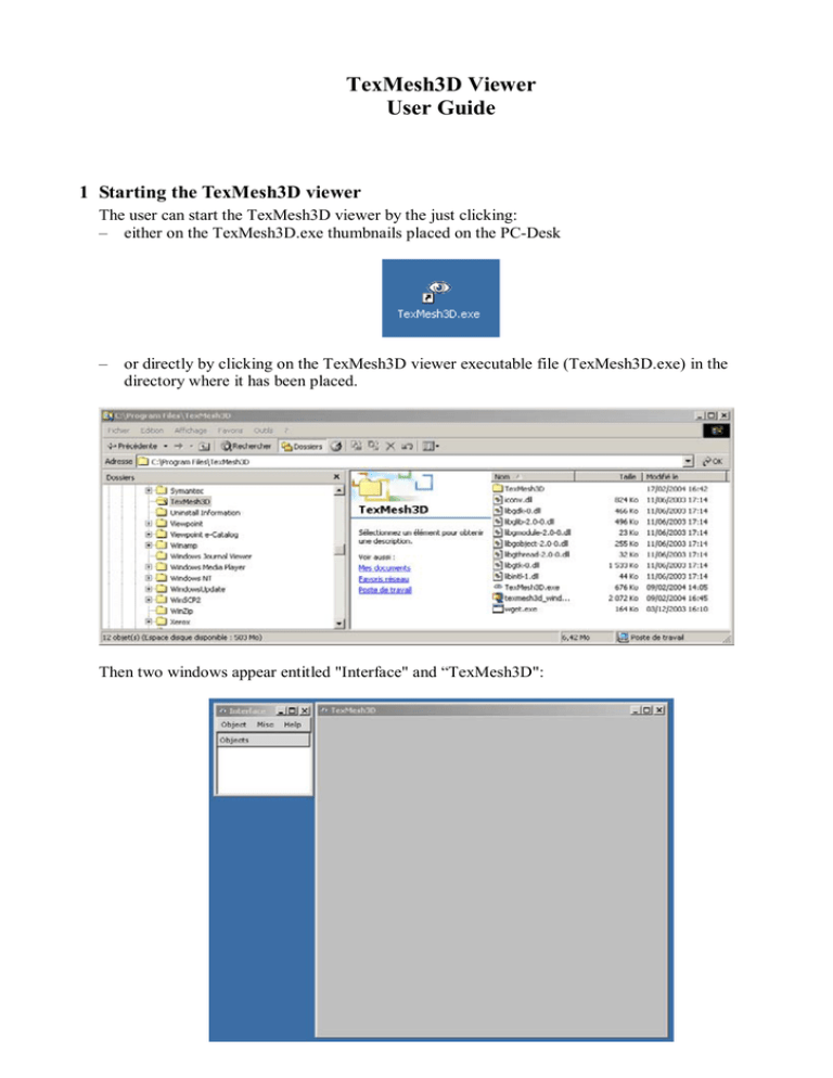
TexMesh3D Viewer User Guide 1 Starting the TexMesh3D viewer The user can start the TexMesh3D viewer by the just clicking: – either on the TexMesh3D.exe thumbnails placed on the PC-Desk – or directly by clicking on the TexMesh3D viewer executable file (TexMesh3D.exe) in the directory where it has been placed. Then two windows appear entitled "Interface" and “TexMesh3D": 2 Loading an object In the "Interface" window, click on “Object” and then on "Add" in the object menu. An "open data file" window appears. Navigate through the discs and directories on the left interactive box in order to select the directory containing the .tri files you want to visualize. The list of the files contained in the selected directory appears on the right box. Select by double clicking in the right box the file having a ".tri" extension corresponding to the object to be visualised (twins9_lr.tri in the following example): After loading, the "Interface" window on the left provides buttons for various modes of visualization. The corresponding shaded 3D model appears in shade mode within the "TexMesh3D" window: 3 Moving the 3D model with the mouse For zooming, place the mouse cursor on the 3D model, click simultaneously the right and left buttons of the mouse, and move upwards for zooming in, and downwards for zooming out. If the mouse has a wheel between its two buttons, you can use it for zooming too. Alternatively, when the "TexMesh3D" window is active (click in to activate it), you can click on the key “z” or key “Z” to zoom in or zoom out, respectively, with predefined zoom factors. For panning (lateral translation of the object), click on the right button of the mouse and drag it in the wanted direction. When the "TexMesh3D" window is active, clicking on the key “p” will limit the mouse only to panning motion in order to centre a region of interest of the object in the window (when clicking either the right or the left button of the mouse). Pressing again the key “p” (toggle) will reactivate the mouse for zoom, panning and rotation interactivity. For rotating, push on the left button of the mouse and drag it horizontally or vertically. The model will rotate around a horizontal and vertical axis, respectively, which are parallel to the window axis at the beginning of the rotation and which remain fixed with the object during the dragging. Then relax the left button of the mouse. The object remains fixed in its new position. If you push again the left button with the cursor inside the “TexMesh3D” window: the two rotation axis are redefined with the new position of the object, parallel to the window axis. With a little practice it becomes very easy to look at an object in any position by just some few successive quick push and drag actions. You can rotate the object around a fixed rotation axis with a constant angle step (default: 10 degrees) by pressing the key “left arrow” (left turn) or the key “right arrow” (right turn). If a param.dat file exists in the current directory, the view points will correspond to the same view points as in the image sequence used to build the model with the GET-ENST 3D object reconstruction technique. For position and camera reset, click on the key “i”, when the "TexMesh3D" window is active. This will reset the position of the virtual camera in exactly the same point of view as from the first image of the original object sequence. 4 Changing the aspect of the 3D model When the "TexMesh3D" window is active, clicking the key “1” will activate the wire representation of the triangular mesh (wireframe drawing mode): When the "TexMesh3D" window is active, clicking the key “2” will activate the shaded representation of the 3D model (Gouraud shading mode, as after loading the object file). When the "TexMesh3D" window is active, clicking the key “3” will activate the direct texture mapping without added synthetic shading (Texture mapping: decal mode): When the "TexMesh3D" window is active, clicking the key “4” will activate the texture mapping with the superposition of the wire representation (Texture mapping: wireframe mode): When the "TexMesh3D" window is active, clicking the key “5” will activate the texture mapping with added synthetic shading (Texture mapping: modulate mode): Each of the above 5 different aspects modes for the visualisation of the 3D model can also be obtained by clicking directly in the "Interface" window on the corresponding mode button (as the Texture decal mode in the figure below): Wire, Shade, Texture decal, Texture wire, Texture modulate, respectively. The Zbuffer mode provides another representation of the object similar to the Shade mode, but computed differently as with the graphic board and without its acceleration: The Data Wire and Data Shade modes allow us to visualise various specific data resulting from the computation. Multiple sets of data may be successively shown by clicking key “<” or key “>” to pass at the next representation. Clicking the "Materials" button in the "Interface" window open a “materials” window. It allows you to change the aspect of the shaded surfaces in modes shade and texture modulate, for example to render the surface in shade mode coloured and more shinny: But the large number of parameters available to control shading are difficult to adjust for a non expert in image synthesis. However convenient reset buttons can be used when the user becomes to be lost. Clicking the "clipping planes" button in the "Interface" window opens open a “clipping planes” window. It allows you to cut the object by enabling/disabling 6 different oriented clipping plans. For each plane you can freely choose the x,y,z coordinates of its normal (in the 3 boxes on the left) and the position of the plane by swiping it along its normal direction by adjusting the cursor on the right. The figure below has been obtained by using two opposite parallel clipping planes : When the "TexMesh3D" window is active, clicking the key “ENTER” activates or stop the light mode (toggle). An extension appears in the "Interface" window. You can chose in this extension the direction of lighting by rotating the object with the mouse as in the "TexMesh3D" window: When the "TexMesh3D" window is active, clicking the key “s” activates or stop the shadow rendering (toggle). If you want to capture an image of the current “TexMesh3D” window you have just to press the key “c” (image in png format) or on the key “C” (vector image in eps format) when the "TexMesh3D" window is active. The eps format can be included in word or LaTeX files. It is well adapted to print in postscript wireframe figures without aliasing effects as the pixelisation of lines and triangle edges. You can also save the current state of the camera corresponding to the “TexMesh3D” window by just pressing the key “.” (dot). This allows you to retrieve the same viewpoint later in another session by loading the camera state by pressing the key “SPACE”. The key “b” (toggle) allows you to visualize an image of the original sequence with the 3D model in exactly the same position (but behind the image). Key “t” (toggle) puts the image in semitransparency. This allows you to compare simultaneously the 3D reconstructed model with the original image. You can go from an original image to the next:previous one by pressing the key “left arrow” (left turn) or the key “right arrow” (right turn). The images of the original sequence must be in a directory named seq laying at the same level as the loaded file tri. Similarly the key “v” (toggle) allows you to visualize the object silhouette in the same image of the original sequence. The keys “left arrow”, “right arrow and “t” can also be used. The silhouettes must lay in a directory named sil laying at the same level as the loaded file tri. In the "Interface" window click on "Help", then on "About" in the Help menu. You will get the following window (on the right) which contents the list of all the key shortcuts available to the user when interacting with the TexMesh3D viewer:


