HMO3004 - Helmar
advertisement

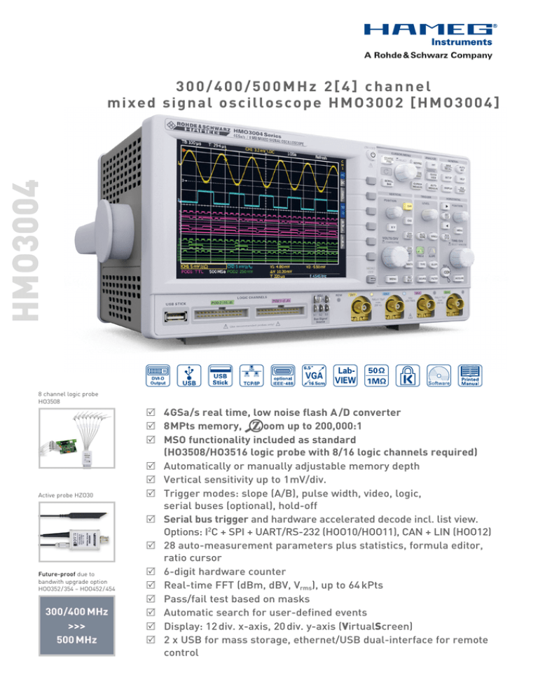
HMO3004 300/400/500MHz 2[4] channel mixed signal oscilloscope HMO3002 [HMO3004] 8 channel logic probe HO3508 Active probe HZO30 Future-proof due to ­bandwith upgrade option HOO352 / 354 – HOO452 / 454 300/400 MHz >>> 500 MHz R 4 GSa /s real time, low noise flash A /D converter oom up to 200,000:1 R 8 MPts memory, R MSO functionality included as standard (HO3508/HO3516 logic probe with 8/16 logic channels required) R Automatically or manually adjustable memory depth R Vertical sensitivity up to 1 mV/div. R Trigger modes: slope (A/B), pulse width, video, logic, serial buses (optional), hold-off R Serial bus trigger and hardware accelerated decode incl. list view. Options: I2C + SPI + UART/RS-232 (HOO10/HOO11), CAN + LIN (HOO12) R 28 auto-measurement parameters plus statistics, formula editor, ratio cursor R 6-digit hardware counter R Real-time FFT (dBm, dBV, Vrms), up to 64 kPts R Pass/fail test based on masks R Automatic search for user-defined events R Display: 12 div. x-axis, 20 div. y-axis (VirtualScreen) R 2 x USB for mass storage, ethernet/USB dual-interface for remote control HMO3004 Series 4 channel mixed signal oscillscope HMO3002 Series 2 channel mixed signal oscillscope HMO3032 [HMO3034] 300MHz HMO3042 [HMO3044] 400MHz HMO3052 [HMO3054] 500MHz Firmware: ≥ 5.0 All data valid at 23°C after 30 minute warm-up. Display 16.5 cm (6.5") VGA Color TFT Display: 640 x 480 Pixel Resolution: LED 500 cd / m2 Backlight: 50 Pts / div. Display area for traces: 400 x 600 Pixel (8 x 12div.) without menu 400 x 500 Pixel (8 x 10div.) with menu 256 colors Color depth: Intensity steps per channel: 0…31 False color, inverse brightness Channel display: up to 2 busses, parallel busses, serial Bus display: busses (option), decoding of the bus values in ASCII, binary, decimal or hexadecimal format; Table view of the decoded data 20 div. vertical for all Math-, Logic-, BusVirtual Screen and Reference Signals 2 steps LED brightness: Vertical System Channels: DSO mode MSO mode CH 1, CH 2 [CH 1…CH 4] CH 1, CH 2, LCH 0…15 (logic channels) with 2 x Option HO3508 Front side [Rear side] Auxiliary input: External Trigger Function 1 MΩ || 14 pF ±2 pF Impedance DC, AC Coupling 100 V (DC + peak AC) Max. input voltage All analog channels on individual choice XYZ-mode: CH 1, CH 2 [CH 1…CH 4] Invert: 300/400/500 MHz (5 mV...5 V) /div. Y-bandwidth (-3 dB): 300 MHz: 180 MHz (1mV, 2 mV)/div. 400 / 500 MHz: 200 MHz (1mV, 2 mV)/div. 2 Hz Lower AC bandwidth: Bandwidth limiter (switchable): approx. 20 MHz 300 MHz: < 1.166 ns Rise time (calculated): 400 MHz: < 0.875 ns 500 MHz: < 0.7 ns 2 % of full scale DC gain accuracy: 12 calibrated steps Input sensitivity: CH 1, CH 2 [CH 1…CH 4] 1mV/div.…5V/div. (1–2–5 Stepping) Between calibrated steps Variable Inputs CH 1, CH 2 [CH 1…CH 4]: 1 MΩ II 13 pF ±2 pF (50 Ω switchable) Impedance DC, AC, GND Coupling 1 MΩ: 200 Vp, derates at 20 dB/Decade to Max. input voltage 5 Vrms above 100 kHz 50 Ω: < 5 Vrms, max. 30 Vp Measuring Category 0 Measuring circuits: ± 8 divs Position range: Offset control: ± 0.2 V - 8 div. * sensitivity 1 mV, 2 mV ± 1 V - 8 div. * sensitivity 5…20 mV ± 2.5 V - 8 div. * sensitivity 50 mV ±20V - 8div. * sensitivity 100mV, 200mV ± 50 V - 8 div. * sensitivity 500 mV...5 V With Option HO3508 / HO3516 Logic channels: Select. switching TTL, CMOS, ECL, 2 x User -2 V…+8 V thresholds 100 kΩ || < 4 pF Impedance DC Coupling 40 V (DC + peak AC) Max. input voltage Triggering Trigger modes: Auto Norm Single Trigger display: Trigger sensitivity: Intern Ext. trigger via Ext. Sensitivity Triggers automatically even when no trigger event occurs for a certain time Always triggers when a trigger event occurs Triggers once on a trigger event LED ≥5 mV / div.: 0.8 div. ≥2 mV / div. …<5 mV / div.: 1div. <2 mV / div.: 1.5 div. Auxiliary Input [Aux. Input rear side] 0.5 V…10 Vpp Trigger level range: With auto level Without auto level External Trigger types: Slope: Slope direction Sources Coupling Auto level Adjustability of the level between the peak values of the signal -8 div.…+8 div. -5 V...+5 V Rising, falling, both CH 1, CH 2, Line, Ext [CH 1…CH 4, Line, Ext.] Adjustability of the level between the peak values of the signal, 5 Hz...300/400/400 MHz 5 Hz...300/400/400 MHz AC 0...300/400/400 MHz DC 30 kHz...300/400/400 MHz HF 0…5 kHz, selectable for DC, Auto level LF Noise rejection (low-pass) 100 MHz, selectable for DC, AC, Auto level Pulse width: Positive, negative Polarity ti>t, ti<t, ti=t, ti/=t, t1<ti<t2, not (t1<ti<t2) Functions 16 ns…8.589 s, resolution 4 ns/1 µs Pulse duration Pos./neg. sync. impulse Video PAL, SECAM, NTSC, PAL-M, SDTV 576i, Standards HDTV 720p, HDTV 1080i, HDTV 1080p Upper, lower, both Fields All, line number selectable Line CH 1, CH 2, Ext. [CH 1…CH 4] Source Logic: AND, OR, TRUE, FALSE, with or without Logic functions evaluation of the duration of the logic operation ti>t, ti<t, ti=t, ti/=t, t1<ti<t2, not (t1<ti<t2), Duration functions Timeout 4 ns...1 s Duration LC0…15 Source LC0…15 X, H, L State Serial Busses: (Options) Start, Stop, ACK, NACK, Address/Data I2C Start, End, Serial Pattern (32Bit) SPI Startbit, Frame Start, Symbol, Pattern UART/RS-232 Frame Start, Wake Up, Identifier, Data, Error LIN Frame Start, Frame End, Identifier, Data, CAN Error 50 ns...>10 s Trigger Holdoff: nd 2 Trigger (B): Slope trigger Type Rising or falling Slope direction 0.8 div. Min. signal height CH 1, CH 2, Ext. [CH 1...CH 4] Source Coupling (source B/=A): DC, HF, NR Coupling (source B=A): see trigger A -8 div.…+8 div. (adjustable separately by A) Level (source B/=A): see level A Level (source B=A): 0…300 / 400 / 500 MHz Frequency range Operating modes: 16 ns...8.589 s, resolution 4 ns/1 µs Time based 1…216 Event based Horizontal System Domain representation: Representation Time Base: Memory Zoom: Time Base: Accuracy Aging Refresh operating modes Roll operating modes Deskew: Step size Search functions: Marker: Digital Storage Sampling rate: Resolution (vertical): Memory: Operation modes: Interpolation: Time, Frequency (FFT), Voltage (XY) Main-window, main- and zoom-window Up to 200,000:1 15 ppm ±5 ppm/year 1 ns/div.…20 ms/div. 50 ms/div.…50 s/div. -62,5 ns…+61,5 ns 500 ps Slope, Pulse, Peak, Rise-/Falltime, Runt up to 8 user definable marker for easy navigation; automatic marker function based on search criteria 2 x 2 GSa/s, 1 x 4 GSa/s [4 x 2 GSa/s, 2 x 4 GSa/s] Logic channels: 16 x 1 GSa/s 8 Bit, HiRes 10 Bit 2 x 4 MPts [4 x 4 MPts], 1x 8 MPts [2 x 8 MPts] Refresh, Average (1024), Envelope, Peak-Detect (500ps), Filter, Rol (free run/ triggered from time base 50 ms/div. and slower), HiRes CH 1...CH 4: Sinx/x, Pulse, Linear; LC0...15: Pulse Persistence: Delay pretrigger: posttrigger Display refresh rate: Display: Off, 50 ms…∞ 0…4 Million x (1/samplerate), Interlaced x2 0…8,59 Billion x (1/samplerate) Up to 4,800 waveforms/s Dots, vectors (interpolation), ‘persistence’ Operation/Measuring/Interfaces Menu-driven (multilingual), Autoset, Operation: help functions (multilingual) Frequency counter: 0.5 Hz…300/400/500 MHz 6 Digit resolution 15 ppm Accuracy ±5 ppm/year Aging Vpp, Vp+, Vp-, Vrms, Vavg, Vtop, Vbase, amplitude, Auto measurements: phase, frequency, period, risetime 80 / 90 %, falltime 80 / 90 %, pos./neg. pulse width, pos./neg. duty cycle, standard deviation, delay, pos./neg. edge count, pos./neg. pulse count, trigger period, trigger frequency Min., max., mean, standard deviation, Statistic number of measurements for up to 6 Functions simultaneously ∆V, ∆t, 1/∆t (f), V to GND, Vt related to Cursor measurements: Trigger point, ratio X and Y, pulse count, edge count, peak to peak, peak+, peak-, mean value, RMS value, standard deviation, rise time, duty cycle 8 MByte for references, device settings and Application memory: formulars Interface: 2x USB-Host (type A) (1x front side, 1x rear Internal side), mass storage (FAT16/32) HO730 Dual-Interface Ethernet/USB-Device Exchangeable (type B) DVI-D (480 p, 60 Hz) for external display, Video OUT: HDMI compatible BNC (rear side), Modes: Trigger, Mask Trigger OUT: USB-Device/RS-232 Dual-Interface Optional: (HO720), IEEE-488 (GPIB) (HO740) Mathematic functions Quickmath: Editor for formula sets: Label for: Sources: Targets: Functions: Display: Mask test: Quickview: General Information Probe ADJ Output: 1 kHz/1MHz square wave signal approx. 0,2Vpp (ta <4 ns) SPI, I2C, UART, retangle, 4Bit counter, Bus Signal Source (4Bit): 4 Bit random pattern Internal RTC (Realtime clock): Date and time for stored data 100...240 V, AC 50…60 Hz, CAT II Line voltage: Max. 70 [90] W Power consumption: Safety class I (EN61010-1), CSA (pending) Protective system: +5…+40 °C Operating temperature: -20…+70 °C Storage temperature: 5…80 % (non condensing) Rel. humidity: Kensington Lock Theft protection: 285 x 175 x 220 mm Dimensions (W x H x D): 3.6 kg Weight: Accessories supplied: HO730 Dual-Interface Ethernet/USB-Device, Line cord, printed operating manual, 2 [4] Probes, 10:1 with attenuation ID (HZ350 400/300MHz, HZ355 500MHz), Software-CD Recommended accessories: HOO10Serial bus trigger and hardware accelerated decode, I2C, SPI, UART/RS-232 on Analog channels and Logic channel HOO11Serial bus trigger and hardware accelerated decode, I2C, SPI, UART/RS-232 on Analog channels HOO12Serial bus trigger and hardware accelerated decode, CAN, LIN on Logic channels and Analog channels HO3508 Active 8 Channel Logic Probe HO3516 2 x HO3508, active 8 Channel Logic Probes HO720 Dual-Interface USB-Device/RS-232 HO740 Interface IEEE-488 (GPIB), galvanically isolated HZ46 4RU 19" Rackmount Kit HZ99 Carrying Case for protection and transport HZ355 Slimline Probe 10:1 with automatic identification HZ355DU Upgrade from 2 x HZ350 to 2 x HZ355 HZO20 High voltage probe 1000:1 (400MHz, 1000Vrms) HZO30 Active probe 1GHz (0.9pF, 1MΩ, including many accessories) HZO40 Active differential Probe 200MHz (10:1, 3,5pF, 1MΩ) HZO41 Active differential Probe 800MHz (10:1, 1pF, 200kΩ) HZO50 AC/DC Current probe 30A, DC…100kHz HZO51 AC/DC Current probe 100/1000A, DC…20kHz ADD, SUB, MUL, DIV Max. 5 formulas per formula set Math. memories and formula set All channels and math. Memories, constants Math. memories ADD, SUB, 1/X, ABS, MUL, DIV, SQ, POS, NEG, INV, SQR, MIN, MAX, LOG10, LN, Integral, Differential, High-pass filter, Low-pass filter Up to 4 math. memories with label Signal test (pass/fail) based on previously defined mask Display of Vp+, Vp-, RMS value, rise time, fall time HMO3000E/230813 · C&E · Subject to change without notice · © HAMEG Instruments GmbH® · DQS-certified in accordance with DIN EN ISO 9001:2008, Reg.-No.: 071040 QM08 HAMEG Instruments GmbH · Industriestr. 6 · D-63533 Mainhausen · Tel +49 (0) 6182 8000 · Fax +49 (0) 6182 800100 · www.hameg.com · info@hameg.com


