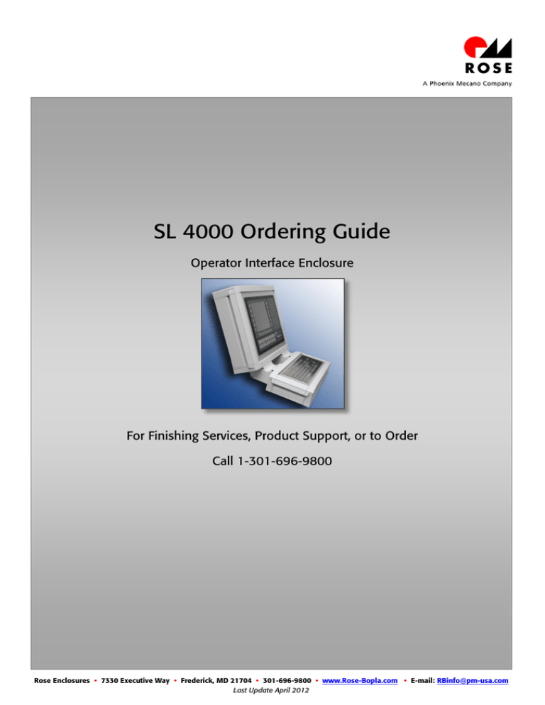
SL 4000 Ordering Guide
advertisement

SL 4000 Ordering Guide Operator Interface Enclosure For Finishing Services, Product Support, or to Order Call 1-301-696-9800 Rose Enclosures • 7330 Executive Way • Frederick, MD 21704 • 301-696-9800 • www.Rose-Bopla.com • E-mail: RBinfo@pm-usa.com Last Update April 2012 SL 4000 Inquiry Order Please copy, fill out and fax: 301-696-9494 Company Telephone Contact Fax Address E-Mail Operational enclosure Profies Profile 1 (Mounting depth =80mm) Front panel Profile 3 (Mounting depth =190mm) Without front panel With front panel Color Profile 2 (Mounting depth =130mm) Standard required connector surface W x H (mm) x Profile RAL 7035, corner pieces RAL 7035, corner caps RAL 7035 Natural anodized profile, Corner pieces RAL 9007, corner caps RAL 9007 Special colors please specify RAL color for each) Profile RAL corner pieces RAL anodized profile Door / Rear wall Door Lock types turn bolt fastener small corner pieces RAL left hinged corner caps RAL corner caps RAL right hinged Lock types turn bolt fastener large square (6 mm) triangular (6.5 mm) square (8 mm) triangular (7 mm) square (7 mm) triangular (8 mm) double ward (3 mm) slot (1.5 mm) Rear wall screwed snap lock (fast lock system) Modified acc. drawing no. (please enclose) Modifications Front plate Modified acc. drawing no. Cutting W x H (mm) (please enclose) x and / or manufacturer/type of controller Position description of cutting Drill holes diameter (mm) number Position description of drilling(s) Other front plate modifications / special versions Profile Modified acc. drawing no. Cutting W x H (mm) (please enclose) x Position description of cutting Drill holes diameter (mm) number Position description of drilling(s) Other front plate modifications / special versions Connection – Suspension system GTKe GT 48/2 Profile 1 / 2 / 3 GT 50/2 GT 60/2 Profile 2 / 3 GT 80/2 GTK 80 GTN II Profile 3 Moterm (linkage only from below) Profile 1 / 2 / 3 external system (please name drawing and manufacturer) Side A (above) Side B (below) Rear wall (on request) 9 Inquiry Order Please copy, fill out and fax: 301-696-9494 Accessories Handles Number Side(s) Standard (order no.): Special length (mm) Hinge set Hinge side Side C (left) Side D (right) Any further information of the position Wall holder set Position (Side) Side C (left) Side D (right) Any further information of the position Document holder Position (Side) A (left) B (right) Any further information of the position Fixing set Single interfaces (IP 65) Spring nut set M4 (8 pieces) number Spring nut set M5 (8 pieces) number RJ45 USB Any further information to front panel interfaces (requirements, position etc.) Multiple interfaces Interfaces and power supplies for optional mounting on the front plate, rear wall or side of the profile 3. Flap Power outlets (Screw terminals) USA (NEMA 5-15) Australia China (C C C) Denmark Germany (VDE) England (BS) France (UTE) India (IS 1293) Italy (CEI 23-16) Schwitzerland Data interfaces SUB-D9 (Socket) number SUB-D9 (Plug) number SUB-D15 (Socket) number RJ12, 6-pol. plastic number RJ45, 8-pol. metal, CAT5e (Socket/Socket) number USB (Socket/Socket) number Position Front panel Rear wall (door) Side profile (profile 3) Any further information to front panel interfaces (requirements, position etc.) 10 Inquiry Order Please copy, fill out and fax: 301-696-9494 Console attachment Profile 1 (Depth = 80mm) Profile type Front panel Profile 2 (Depth = 130mm) Without front plate With front plate Color Standard required connector surface W x H (mm) x Profile RAL 7035, corner pieces RAL 7035, corner caps RAL 7035 corner pieces RAL 9007, corner caps RAL 9007 Special colours (please specify RAL colour for each) Profile RAL corner pieces RAL Natural anodized profile corner pieces RAL corner caps RAL corner caps RAL Rear wall Standard screwed other (on request) Modifications Front plate Modified acc. drawing no. Cutting W x H (mm) (please enclose) x and/ or manufacturer/type of controller Position description of cutting Drill holes diameter (mm) number Position description of drilling(s) Other information on the front panels Profile Modified acc. drawing no. Cutting W x H (mm) (please enclose) x Position description of cutting Drill holes diameter (mm) number Position description of drilling(s) Other front plate modifications / special versions 11


