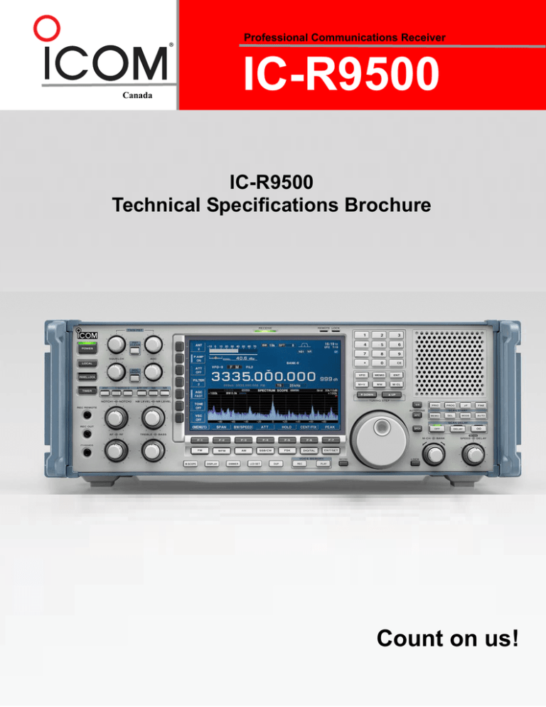
Professional Communications Receiver
Canada
IC-R9500
IC-R9500
Technical Specifications Brochure
Count on us!
IC-R9500 SPECIFICATIONS
Professional Communications Receiver
Canada
Frequency
Range for Canada
Range for USA
Resolution
Tuning steps – fixed
Tuning steps – program
Digital IF PBT and Notch Filters
0.005 – 3335 MHz
0.005 – 821.999999 MHz,
851 – 866.999999 MHz
896 – 3335 MHz
1 Hz
1, 10, 100 Hz; 1, 2.5, 5, 6.25, 9, 10,
12.5, 20, 25, 100 kHz, 1 MHz
Can specify which steps are ON for
each reception mode
One for each reception mode
0.1 to 999.9 kHz in 0.1 kHz increments
Stability
At room temperature
-8
< ± 5 x 10 (+25º C )
(after 5 min warm up)
With temperature change < ± 5 x 10⁻⁸ (0º C to +50º C)
-7
Aging rate
< ± 1 x 10 per year
Reception Modes and Features
Reception modes
Reception features
AM
FM
SSB
CW
Analog TV tuner
USB, LSB, CW, FSK, AM, FM,
WFM, P25*
* Optional UT-122 required
Synchronous (S-AM);
upper, lower or both sidebands;
auto tuning function ± 5 kHz (nominal)
AFC function
Auto tuning function ± 1 kHz (nominal)
Normal and reversed (opposite side
band); auto tuning function ± 500 Hz
(nominal); audio peak filter (APF) to
enhance audio
NTSC, PAL, SECAM
(Except USA version)
Notch filter - manual
Width
Rejection
Center frequency range
(nominal)
200 Hz to 10 kHz in 200 Hz steps
50 to 500 Hz in 50 Hz steps;
600 to 3600 Hz in 100 Hz steps
(2700 Hz max for FSK)
FM
7, 15, 50 kHz
WFM
180 kHz
P25
15 kHz (optional UT-122 required)
Shape
Sharp, soft
Selectivity
(with sharp shape)
SSB, FSK (BW=2.4 kHz) -3 dB: >2.4 kHz
-60 dB: <3.6 kHz
shape factor <1.5:1
CW (BW=500 Hz)
-3 dB: >500 Hz
-60 dB: <700 Hz
shape factor <1.4:1
AM (BW=6 kHz)
-3 dB: >6.0 kHz
-60 dB: <15.0 kHz
shape factor <2.5:1
FM (BW=15 kHz)
-3 dB: >12.0 kHz -60 dB: <25.0 kHz
shape factor <2.1:1
WFM (BW=180 kHz)
-6 dB: >180 kHz
Twin with graphical display
For SSB, AM, FM, WFM
Attenuates up to 3 beat tones
For SSB, CW, AM, FSK
Wide, middle, narrow
> 70 dB at two points
SSB: -1060 to + 4400 Hz
CW: CW pitch freq. ± 2540 Hz
AM: ± 5100 Hz
Dynamic Range
Roofing filter bandwidths
st
(IF Prefilter at 1 IF)
Third-order intermodulation
distortion
IP3 at 14.1 MHz
IP3 at 50 MHz
IP3 at 620 MHz
IP3 at 30 MHz to 3335
rd
Dynamic range (3 order IMD)
3, 6, 15, 50 kHz, (except WFM)
240 kHz (WFM only)
(100 kHz separation,
Pre-amp OFF, AGC OFF)
> +40 dBm
> +9 dBm
> +6 dBm
+5 dBm (typical)
109 dB (typical) at 14.1 MHz;
(100 kHz separation,
Pre-amp OFF, AGC OFF)
Spurious and image rejection
0.1 – 30 MHz
30 – 2500 MHz
2500 – 3000 MHz
Oscillator phase noise
0.1 – 30 MHz
30 – 1500 MHz
> 70 dB
> 50 dB
> 40 dB
(typical)
<-120 dBc/Hz at 10 kHz offset
<-100 dBc/Hz at 10 kHz offset
Signal Level Meter (RSSI)
Units
S-meter, dBμ, dBμ(emf), dBm
(Only S-meter for WFM)
0.1 dB
± 3 dB for 10 to 70 dBμ signal from
100 kHz to 3335 MHz at 25º C
Resolution
Accuracy
Digital IF Bandpass Filter
Bandwidths
AM
SSB, CW, FSK
Pass band tuning (PBT)
Notch filter – auto (ANF)
ATT = 0 dB, Pre-amp ON or OFF
Sensitivity
SSB, CW,
AM
FM
FM 50 kHz WFM
FSK
–
–
–
0.100 – 1.799 MHz*
0.5 μV
6.3 μV
–
1.800 – 29.999 MHz*1
0.2 μV
2.5 μV 0.5 μV*3 0.71 μV*3
30 – 2999.999 MHz*2
0.32 μV
3.5 μV 0.5 μV
0.71 μV 1.4 μV
2
3000 – 3335 MHz*
1.0 μV
11 μV 1.6 μV
2.2 μV
4.5 μV
*1 Pre-amp 1 ON
*2 Pre-amp ON
*3 f = 28 – 29.999 MHz
SSB, FSK BW= 2.4 kHz at 10 dB S/N
CW BW= 0.5 kHz at 10 dB S/N;
AM BW = 6.0 kHz at 10 dB S/N
FM BW=15 kHz at 12 dB SINAD;
FM 50 k BW=50 kHz at 12 dB SINAD
WFM BW=180 kHz at 12 dB SINAD
Frequency
1
Noise figure
1.800 – 29.999 MHz
30 – 1599.999 MHz
1600 – 2999.999 MHz
AMATEUR | AVIONIC | LAND MOBILE | MARINE | RECEIVER
(typical)
< 5.5 dB Pre-amp 1 ON
< 6.5 dB Pre-amp ON
< 8.0 dB Pre-amp ON
IC-R9500 SPECIFICATIONS
Professional Communications Receiver
Canada
Amplitude
Receiver Front-End
Input BPF unit
HF bands
VHF/UHF
th
11 switched, 5 -order BPF
th
11 switched, 7 -order LPF and
th
7 -order HPF
Attenuator
HF bands
30 – 1150 MHz
1150 – 3335 MHz
6, 12, 18, 24, 30 dB
10, 20, 30 dB
20 dB only
Pre-amp gain
HF bands
30-2000 MHz
2000 – 3000 MHz
10 dB (nominal) or high-gain
10 dB (nominal)
5 to 10 dB (nominal)
AGC time constant (60 dB)
AM, SSB, CW, FSK
Fast, Mid, Slow
(time constant can be set for the 3
settings for each reception mode)
1
1
0.1* , 0.2* , 0.3, 0.5, 0.8, 1.2, 1.6, 2.0,
2
2
3.0, 4.0, 5.0, 6.0, 7.0* , 8.0* seconds
*1 0.1 and 0.2 only for SSB, CW, FSK
*2 7.0 and 8.0 only for AM
FM, WFM, P25
Manual RF gain control
Noise blanker
Noise reduction
Fixed at 0.1 second
> 90 dB range
Two independent with settable depth
and width
Reduces random noise components
Spectrum Scope
Intermediate Frequencies
st
1
nd
2
rd
3
4
th
58.7 MHz (0.1 – 29.99999 MHz)
778.7 MHz (30.0 – 499.99999 MHz);
278.7 MHz (500.0 – 3335 MHz)
10.7 MHz (0.1 – 29.99999 MHz)
58.7 MHz (30.0 – 3335 MHz)
48 kHz (0.1 – 29.99999 MHz)
10.7 MHz (30.0 – 3335 MHz)
None (0.1 – 29.99999MHz)
48 kHz (30.0 – 3335 MHz)
Memory Channels
Regular memory
Auto memory write
Skip memory
Scan edge memory
Channel parameters stored
(for regular memory)
Memory banks
VFO channel memory
1000 channels
100 channels
100 channels
20 channels
Frequency, mode, filter, tuning step,
name, antenna, pre-amp, attenuation,
tone
13 for grouping channels
10 channels
Scan types
40 channels per second in memory
scan mode
Programmed, ΔF, memory, select
memory, priority, mode select
memory, auto memory write, tune
Squelch
Sensitivity
FM
SSB
AM
WFM
Range
Voice squelch control
(VSC)
Tone/DTCS squelch
Resolution bandwidth
Sweep speed
Display dynamic range
Attenuator
Peak marker function
Max hold function
Wide mode
Frequency span
Resolution bandwidth
Center and Fixed
±(2.5, 5, 10, 25, 50, 100, 250, 500)kHz
±(1, 2.5, 5) MHz
0.2, 0.5, 1, 2, 5, 10, 20 kHz
(some spans have fewer bandwidths)
6 speeds available
90 dB
10, 20, 30 dB
peak excursion 0 to 80 dB; peak
threshold -100 to 0 dB; 1 dB steps
Displays maximum levels until reset
(AF output muted)
±(5, 10, 25, 50, 100, 250, 500) MHz
20 kHz
Display
Type
Resolution
Size
Color TFT LCD
800 x 480 pixels
180 mm (7.0 in) diagonal (nominal)
Saving and Recording
Multi-scan Functions
Scan speed
Normal mode
Span modes
Frequency span
1.8 – 2999.999 MHz, pre-amp ON
< 1.0 μV
< 4.0 μV
< 6.0 μV
< 6.0 μV
> 85 dB (typical)
Opens squelch only when receiving a
modulated signal
Opens squelch only when receiving a
signal containing a matching
subaudible tone (51 tones available) or
DTCS code (104 codes available)
Data files
Digital voice recorder
normal mode
Sampling rate
Recording time - internal
Digital voice recorder
short mode
AMATEUR | AVIONIC | LAND MOBILE | MARINE | RECEIVER
Memory channel contents can be
saved and recalled from built-in CF
(Compact Flash) memory card or USB
memory.
Record to internal CF card or external
USB memory
8, 12, 16, 24, 48 kHz (WAV format)
60 min with 16 kHz sampling rate and
128 MB CF card (nominal)
Allows playback of last 5 to 30
seconds
IC-R9500 SPECIFICATIONS
Professional Communications Receiver
Canada
Inputs and Outputs
Antenna HF (< 30 MHz)
Antenna 30 – 1149.99999
MHz
Antenna 1150 – 3335 MHz
Antenna Select
Reference In/Out 10 MHz
IF Out
Ext Speaker
S/P DIF Out
Video In
Video Out
Ext Display
Detector Out
Speech Out
Line Out
Phones (front panel)
Record Out (front panel)
Record Remote (front/rear)
DC Out
Accessory
SO-239 50 Ω (nominal)
Phono (RCA) 500 Ω (nominal)
Reverse power protection 5 W (nom.)
Type-N 50 Ω (nominal)
Type-N 50 Ω (nominal)
2-conductor 3.5 mm (⅛ in) 13.8 V DC,
100 mA max
BNC, -10 dBm, 50 Ω (nominal)
BNC, 10.7 MHz;
level same as antenna input signal,
or less when AGC or atten is on
2-conductor 3.5 mm (⅛ in)
> 2.6 W at 10% distortion with an 8 Ω
load (nominal)
Optical, 48 kHz 16-bit
Phono (RCA)
Phono (RCA) for TV signal
(no signal out on USA version)
15-pin mini D-SUB; VGA compatible
2-conductor 3.5 mm (⅛ in)
Phono (RCA)
Phono (RCA)
3-conductor 3.5 mm (⅛ in)
3-conductor 3.5 mm (⅛ in)
2-conductor 3.5 mm (⅛ in)
15 VDC (nominal), 1 A max
8-pin DIN
General
Operating temperature
range
Power supply req. AC
Power supply req. DC
Power consumption AC
Dimensions (W x H x D)
(projections not included)
Weight
LAN
RS-232C
Data In
Remote CI-V
USB Type “A”; USB 1.1/2.0
Output current 500 mA max
For USB memory, hub, or keyboard
(Save/Load memory and settings; edit
channel memory with keyboard)
RJ45 10BaseT/100BaseT
For firmware updates using a PC
9-pin mini D-SUB; for remote control
by a PC or transceiver operation
8-pin DIN; CI-V for remote control
(requires optional CT-17 CI-V level
converter)
3-conductor 3.5 mm (⅛ in)
CT-17
UT-122
SP-20
Shipping crate
All features and specifications may be subject to change without notice or obligation.
Phone: 604.952.4266 Fax: 604.952.0090
100/120/230/240 V 47 to 63 Hz
13.5 to 15 V DC (negative ground)
from a regulated DC supply of ≥10 A.
Not to be connected to an unregulated
power source such as a vehicle
battery.
< 100 VA
424 x 149 x 340 mm
16 11/16 x 5 7/8 x 13 3/8 in
20 kg; 44 lb (nominal)
Options
Data Interfaces
USB
0º C to +50º C; +32º F to +122º F
www.icomcanada.com
CI-V Level Converter
For remote receiver control using a PC
with RS-232C
P25 Digital Unit
provides APCO P25 digital mode
reception
External Speaker
Dimensions: 74 x 81 x 86 cm
29 x 32 x 34 in
IC-R9500 Rear View
#150-6165 Highway 17, Delta, BC, V4K-5B8
All materials have been prepared by ICOM Canada and rights are reserved. ©2007 ICOM Canada Inc.
3/22/2007


