ASW-80G1
AeroScape LED Large Housing Wall and Surface Mount Series
Type:
Job:
Approvals:
Catalog Number:
ASW
-
# of
LEDs
Series
Driver
NW
-
LED
Color
Distribution
Voltage
Mounting
Options
Finish
Accessories
Date:
Page 1 of 6
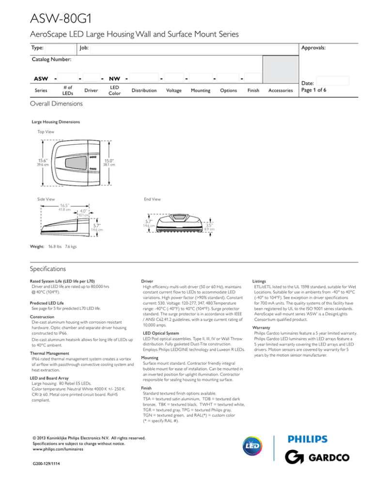
Overall Dimensions
Large Housing Dimensions
Top View
15.6”
Side View
15.6”
15.0”
15.6”39.6 cm
39.6 cm
15.0”38.1 cm
38.1 cm
End View
16.5”
16.5”41.8 cm
4.0”
41.8 cm
4.0” 10.1 cm
16.5”
4.0”
10.1 cm
5.7”
5.7” 14.6 cm
14.6 cm
8.9 cm
38.1 cm
41.8 cm
10.1 cm
3.5”
3.5” 8.9 cm
15.0”
39.6 cm
5.7”
14.6 cm
3.5”
8.9 cm
5.7”
14.6 cm
Weight: 16.8 lbs 7.6 kgs
Specifications
Rated System Life (LED life per L70)
Driver and LED life are rated up to 80,000 hrs
@ 40°C (104°F).
Predicted LED Life
See page for 5 for predicted L70 LED life.
Construction
Die-cast aluminum housing with corrosion resistant
hardware. Optic chamber and separate driver housing
constructed to IP66.
Die-cast aluminum heatsink allows for long life of LEDs up
to 40°C ambient.
Thermal Management
IP66 rated thermal management system creates a vortex
of airflow with passthrough convective cooling system and
heat extraction.
LED and Board Array
Large housing: 80 Rebel ES LEDs.
Color temperature: Neutral White 4000 K +/- 250 K.
CRI ≥ 60. Metal core printed circuit board. RoHS
compliant.
Driver
High efficiency multi-volt driver (50 or 60 Hz), maintains
constant current flow to LEDs to accommodate LED
variations. High power factor (>90% standard). Constant
current: 530. Voltage: 120-277, 347, 480.Temperature
range: -40°C (-40°F) to 40°C (104°F). Surge protector
standard. The surge protector is in accordance with IEEE
/ ANSI C62.41.2 guidelines, with a surge current rating of
10,000 amps.
LED Optical System
LED Pod optical assemblies. Type II, III, IV or Wall Throw
distribution. Fully gasketed Dust-Tite construction.
Employs Philips LEDGINE technology and Luxeon R LEDs.
Mounting
Surface mount standard. Contractor friendly integral
bubble mount for ease of installation. Can be mounted in
an inverted position for uplight illumination. Contractor
responsible for sealing housing to mounting surface.
Finish
Standard textured finish options available.
TSA = textured satin aluminium, TDB = textured dark
bronze, TBK = textured black, TWHT = textured white,
TGR = textured gray, TPG = textured Philips gray,
TGN = textured green, and RAL(*) = custom color
(* = specify RAL #).
© 2013 Koninklijke Philips Electronics N.V. All rights reserved.
Specifications are subject to change without notice.
www.philips.com/luminaires
G200-129/1114
Listings
ETL/cETL listed to the UL 1598 standard, suitable for Wet
Locations. Suitable for use in ambients from -40° to 40°C
(-40° to 104°F). See exception in driver specifications
for 700 mA units. The quality systems of this facility have
been registered by UL to the ISO 9001 series standards.
AeroScape wall mount series ‘ASW’ is a DesignLights
Consortium qualified product.
Warranty
Philips Gardco luminaires feature a 5 year limited warranty.
Philips Gardco LED luminaires with LED arrays feature a
5 year limited warranty covering the LED arrays and LED
drivers. Motion sensors are covered by warranty for 5
years by the motion sensor manufacturer.
ASW-80G1
AeroScape LED Large Housing Wall and Surface Mount Series
Type:
Job:
Page 2 of 6
AeroScape Wall Mount Large Housing
ASW-80G1
Series
ü ASW
# of LEDs
80G1
Driver
LED Color
530
ü NW
Neutral
White
Distribution
Voltage
2L
Type II
120
3L
Type III
208
4L
Type IV
240
WT
Wall
Throw
277
Mounting
Options7,8
SM
F12
Surface
Mount
(standard)
347
F22
F32
480
UNV1
1) ‘UNV’ universal voltage, 120-277V.
2) Specify voltage. Fusing and photocontrols not available with ‘UNV’ voltage option.
3) ‘PCB’ option not available in 480V.
4) Luminaire efficiency will decrease from 0 to 10% depending on the spread of the optics.
5) 0-10V leads exiting luminaire supplied for connection to external secondary controls (by others).
(120, 277, 347V)
Double Fusing
(208, 240, 480V)
Double Fusing
(208, 240, 480V)
Canadian Double Pull
DS256
DS506
DS756
Dynadimmer
Safety Profile
DM256
DM506
Photocontrol
Button
DM756
SG
Stone Guard
DE256
DL4
Diffuse Lens
DE506
DD5
Dimming Driver
DE756
DCP6
Dynadimmer
Custom
Programming
PCB2,3
Notes:
Single Fusing
6) Dynadimmer options and accessories are only available in 120-277V. Includes Dimming Driver (‘DD’) option.
7) ASW is compatible with a wide range of occupancy sensors, wireless controls and asset
management systems (by others). Contact factory.
Dynadimmer
Median Profile
Dynadimmer
Economy Profile
8) An emergency egress option is available. See spec sheet number WLSP0397.
Accessories (must be ordered separately)
Finish
Textured
Satin Aluminum
F1-KIT2
TDB
Textured
Dark Bronze
F2-KIT2
TBK
Textured Black
TWHT
Textured White
TGR
Textured Gray
TGN
Textured Green
TPG
Textured
Philips Gray
TSA
Distribution Patterns
Single Fusing
Field Installed Kit
(120, 277, 347V)
Double Fusing
Field Installed Kit
(208, 240, 480V)
RAL(*)
F3-KIT2
(208, 240, 480V)
Canadian Double Pull
DYN-KIT1
Type II (2L)
Type III (3L)
Type IV (4L)
Wall Throw (WT)
Dynadimmer USB
Cable Kit
(for field programming)
DYN-KIT2
Dynadimmer Handheld
Programmer Kit
(for field programming)
Custom Color
(*specify RAL #)
© 2013 Koninklijke Philips Electronics N.V. All rights reserved.
Specifications are subject to change without notice.
www.philips.com/luminaires
G200-129/1114
Double Fusing
Field Installed Kit
ASW-80G1
AeroScape LED Large Housing Wall and Surface Mount Series
Type:
Job:
Page 3 of 6
Option Details
F1
Single Fusing (120, 277, 347V)
F2
Double Fusing (208, 240, 480V)
F3
Double Fusing (208, 240, 480V)
PCB
Factory Installed Photocell Button
DD
Dimming Driver (0-10V)
Continuous dimming down to 10% power.
0-10V leads exiting luminaire supplied for connection to external controls (by others).
(Canadian double pull)
Not available with 480 V.
Dynadimmer Details
Note: Voltage must be specified with fusing and photocell options.
SG
Stone Guard (included, field installed)
DCP
Dynadimmer Custom Programming
The Dynadimmer programmer enables users to program the individual Dynadimmer either on or off-site. For factory programming, submittals required to set profile. For field programming,
DYN-KIT1 or DYN-KIT2 required.
Dynadimmer - Safety Profile1
This mode focuses on safety by dimming during a limited period of time.
Decreases light levels to 25, 50, or 75% low during a four hour period. 2
DS25 25% Low
DL
Diffuse Lens
Luminaire efficiency will decrease from
0 to 10% depending on the spread of the optics.
DS50 50% Low
DS75 75% Low
Dynadimmer - Median Profile1
This mode provides an ideal balance between illumination and energy savings.
Decreases light levels to 25, 50, or 75% low during a six hour period. 2
Reduces glare from direct view of optics.
DM25 25% Low
DM50 50% Low
DM75 75% Low
Dynadimmer - Economy Profile1
This mode maximizes energy savings by dimming during a longer period of time.
Decreases light levels to 25, 50, or 75% low during an eight hour period. 2
DE25 25% Low
DE50 50% Low
DE75 75% Low
1) Dynadimmer not available in 347 or 480 V.
2) Can be modified later by the end-user with optional USB cable and free programming software.
Note:
An emergency egress option is available.
See spec sheet number WLSP0397.
Accessory Details
F1-KIT Single Fusing Field Installed Kit (120, 277, 347V)
F2-KIT Double Fusing Field Installed Kit (208, 240, 480V)
F3-KIT Double Fusing Field Installed Kit (208, 240, 480V)
(Canadian double pull)
DYN-KIT1
DYN-KIT2
G200-129/1114
The USB programmng cable is used to directly link and program
Dynadimmer 0-10V from a PC. When using this cable, no programmer tool is needed. Dynadimmer software has a
special button to activate the USB feature. Software available
for free download at www.www.philips.com/lumimaires.com. Cable only.
Dynadimmer Handheld Programmer Kit
(for field programming)
The Dynadimmer programmer enables users to program
the individual Dynadimmer either on or off-site.
Powered by 4 AA or LR6 batteries.
Handheld programmer with cables.
© 2013 Koninklijke Philips Electronics N.V. All rights reserved.
Specifications are subject to change without notice.
www.philips.com/luminaires
Dynadimmer USB Cable Kit (for field programming)
ASW-80G1
AeroScape LED Large Housing Wall and Surface Mount Series
Type:
Job:
Page 4 of 6
Standard Wall Mount Details
Wall Mount Drill Template
3.375”
Bubble
Level
4.39”
11.15 cm
3.375”
5.7”
14.6 cm
Ø2.750”
Ø 3.50”
5.13”
15.6”
39.6 cm
13.03 cm
Photometric Data - ASW-80G1
Cat No.
Optic
(distribution)
3.375”
ASW-80G1-530
3.375”
System
Wattage
Fixture
Lumens
Efficacy
(backlight)
(uplight)
(glare)
CCT
IES File #
128
13,103
102
3
0
3
4000 K +/- 250 K
ASW-80G1-530-2L.IES
13,802
110
3
0
3
4000 K +/- 250 K
ASW-80G1-530-3L.IES
126
13,331
106
3
0
3
4000 K +/- 250 K
ASW-80G1-530-4L.IES
126
14,430
115
4
0
0
4000 K +/- 250 K
ASW-80G1-530-WT.IES
Type5.7”II (2L)*
Type III (3L)
Ø2.750”
Type IV (4L)
Wide Throw (WT) (Type II)
126
15.6”
39.6 cm
Ø 3.50”
B
U
G
* LM-79 test report data was generated by a 3rd party independent lab - Luminaire Testing Laboratory (LTL).
Backlight - refers to light directed opposite the target area, which may create light trespass. Backlight is commonly behind the luminaire.
Uplight
- is illumination directed above the horizontal plane of the luminaire (90°) which causes artificial sky glow.
Glare
- is the amount of light from the luminaire emitted in directions or at angles that cause glare, which can be annoying or visually disabling.
© 2013 Koninklijke Philips Electronics N.V. All rights reserved.
Specifications are subject to change without notice.
www.philips.com/luminaires
G200-129/1114
ASW-80G1
AeroScape LED Large Housing Wall and Surface Mount Series
Type:
Job:
Page 5 of 6
LED Lumen Maintenance Data - ASW-80G1
ASW-80G1 @ 530 mA
5
10
15
20
25
30
35
40
Junction Temperature2
48
53
58
63
68
73
78
83
Thermal Factor
Predicted Life
Hours of operation / Years based on 10 hrs/day burn cycle
Outdoor Ambient Temp (°C)1
1.04
1.03
1.02
1.01
1
0.99
0.98
0.97
0
1.04
1.03
1.02
1.01
1
0.99
0.98
0.97
3
8,000 / 2.2
1.03
1.02
1.01
1.00
0.99
0.98
0.97
0.96
16,000 / 4.4
1.03
1.01
1.00
0.99
0.98
0.97
0.96
0.95
24,000 / 6.6
1.02
1.01
0.99
0.98
0.97
0.96
0.94
0.93
32,000 / 8.8
1.01
1.00
0.98
0.97
0.96
0.94
0.93
0.92
40,000 / 11.0
1.00
0.99
0.97
0.96
0.95
0.93
0.92
0.90
48,000 / 13.2
0.99
0.98
0.96
0.95
0.94
0.92
0.90
0.89
56,000 / 15.3
0.98
0.97
0.95
0.94
0.92
0.91
0.89
0.87
64,000 / 17.5
0.97
0.96
0.94
0.93
0.91
0.90
0.88
0.85
recommendation, and will vary based on drive current and nominal forward voltage of the LED.
3. Thermal factor is a prorate or derate value based on the in-situ solder point measurement and the 72,000 / 19.7
0.96
0.95
0.93
0.92
0.90
0.88
0.85
0.83
80,000 / 21.9
0.95
0.94
0.92
0.91
0.88
0.86
0.83
0.81
88,000 / 24.1
0.94
0.93
0.91
0.89
0.86
0.84
0.81
0.79
96,000 / 26.3
0.94
0.91
0.89
0.87
0.84
0.82
0.79
0.77
104,000 / 28.5
0.92
0.89
0.87
0.85
0.82
0.80
0.77
0.74
112,000 / 30.7
0.90
0.87
0.85
0.83
0.80
0.77
0.74
0.72
120,000 / 32.9
0.88
0.85
0.83
0.81
0.77
0.74
0.72
0.70
128,000 / 35.1
0.86
0.84
0.81
0.77
0.74
0.72
0.69
-
136,000 / 37.2
0.84
0.81
0.77
0.74
0.71
0.69
-
-
144,000 / 39.5
0.80
0.76
0.73
0.70
0.68
-
-
-
152,000 / 41.6
0.75
0.72
0.69
-
-
-
-
-
160,000 / 43.8
0.70
0.67
-
-
-
-
-
-
Notes:
1. Outdoor ambient temperature is based on annual average operating air temperature as seen by the fixture within its environmental conditions.
2. Junction temperature is calculated from in-situ, solder point measurement per LED manufacturers relative luminous flux provided by the LED manufacturer.
4. LED Lumen Maintenance Data chart is actual lumen adjustment per the operating ambient. No additional prorate or derate required.
Notes:
Pb
lead-free
© 2014 Koninklijke Philips N.V. All rights reserved.
Specifications are subject to change without notice.
www.philips.com/luminaires
G200-129/1114
R
oHS
2002/95/EC
Philips Lighting
North America Corporation
200 Franklin Square Drive
Somerset, NJ 08873
Phone: 855-486-2216
Philips Lighting Company
281 Hillmount Road
Markham ON, Canada L6C 2S3
Phone: 800-668-9008

