PACSystems* RX3i
IC695CHS012 and IC695CHS016
Universal Backplanes
GFK-2554A
March 2012
The PACSystems* RX3i Universal Backplanes provide a dual-bus backplane that supports PCI-based
(IC695) and serial (IC693 and IC694) I/O and option modules. The RX3i Universal Backplanes also
support Series 90-30 IO and option modules. See the PACSystems RX3i System Manual, GFK-2314 for
lists of supported modules. The 16-slot Universal Backplane (IC695CHS016), and the 12-slot Universal
Backplane (IC695CHS012) include the following features:
▪
▪
▪
▪
▪
Terminal Strip on the left end for Isolated +24V input
Backplane grounding point
An integral grounding bar for connecting module/shield grounds
Serial Expansion connector for connection to Serial Expansion and Remote Backplanes
Slot numbers printed on the backplane that can be used as a reference for configuration.
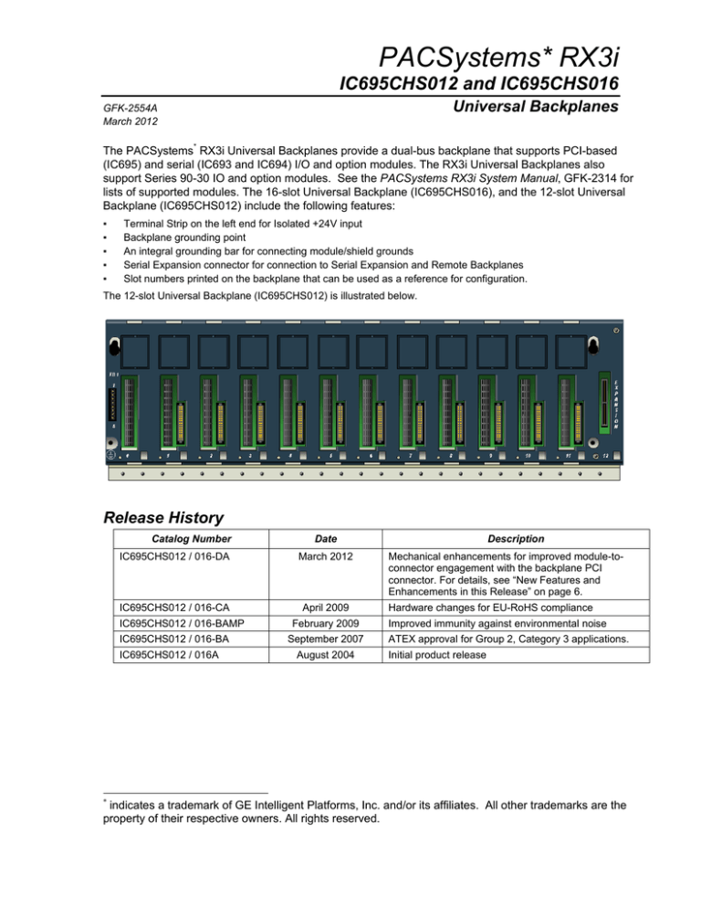
The 12-slot Universal Backplane (IC695CHS012) is illustrated below.
Release History
Catalog Number
IC695CHS012 / 016-DA
IC695CHS012 / 016-CA
IC695CHS012 / 016-BAMP
IC695CHS012 / 016-BA
IC695CHS012 / 016A
*
Date
March 2012
April 2009
February 2009
September 2007
August 2004
Description
Mechanical enhancements for improved module-toconnector engagement with the backplane PCI
connector. For details, see “New Features and
Enhancements in this Release” on page 6.
Hardware changes for EU-RoHS compliance
Improved immunity against environmental noise
ATEX approval for Group 2, Category 3 applications.
Initial product release
indicates a trademark of GE Intelligent Platforms, Inc. and/or its affiliates. All other trademarks are the
property of their respective owners. All rights reserved.
2
RX3i Universal Backplanes
GFK-2554A
UL Class 1 Division 2 & ATEX Zone 2 Hazardous Area Warnings
1.
EQUIPMENT LABELED WITH REFERENCE TO CLASS I, GROUPS A, B, C, D, DIV. 2
HAZARDOUS AREAS IS SUITABLE FOR USE IN CLASS I, DIVISION 2, GROUPS A, B, C, D OR
NON–HAZARDOUS LOCATIONS ONLY.
2. WARNING – EXPLOSION HAZARD – SUBSTITUTION OF COMPONENTS MAY IMPAIR
SUITABILITY FOR CLASS I, DIVISION 2 & ATEX ZONE 2.
3. WARNING – EXPLOSION HAZARD – DO NOT DISCONNECT EQUIPMENT UNLESS POWER HAS
BEEN SWITCHED OFF OR THE AREA IS KNOWN TO BE NON–HAZARDOUS.
ATEX Zone 2 Hazardous Area Requirements
In order to maintain compliance with the ATEX Directive, an RX3i system located in a Zone 2 area
(Category 3) must be installed within a protective enclosure meeting the criteria detailed below:
IP54 or greater, and
Mechanical strength to withstand an impact energy of 3.5 Joules
RX3i Universal Backplane Installation
The RX3i system and its components are considered open equipment (having live electrical parts that may be
accessible to users) and must be installed in a protective enclosure or incorporated into other assemblies
manufactured to provide safety. As a minimum, the enclosure or assemblies must provide protection equivalent to a
NEMA/UL Type 1 enclosure or an IP20 rating (IEC60529). The enclosure must be able to adequately dissipate the
heat generated by all of the components mounted inside so that no components overheat. A minimum space of at
least 102mm (4 inches) as shown below is required on all sides of the RX3i backplane for cooling. Additional space
may be required, depending on the amount of heat generated by the equipment during operation. Please refer to the
PACSystems RX3i System Manual, GFK-2314, for information about enclosures and heat dissipation.
Backplane Orientation
Backplanes must be mounted horizontally to meet product
performance and reliability specifications by providing
adequate airflow around the modules. Other mounting
orientations may affect system performance and/or reliability
and are therefore not recommended.
RX3i Universal Backplanes
3
GFK-2554A
Backplane Dimensions and Spacing
102mm *
(4.00in)
12-Slot 16-Slot
462mm 604.3mm
(18.19in) (23.791in)
102mm *
(4.00in)
12-Slot 16-Slot
428mm 570.2mm
(16.85in) (22.45in)
Universal
Backplane front
view
90mm
(3.54in)
5.08mm
0.20 dia.
typical
102mm *
(4.00in)
141.5mm
(5.57in)
102mm *
(4.00in)
31.5mm
(1.24in)
* Allowance for cooling
148mm
(5.83in)
Side dimension is for standard modules with
doors closed.
Universal
Backplane with
Modules installed
side view
Side dimension does not include extra depth
required for cables and connectors.
Modules with Extended High-Density
Terminal Blocks (such as Terminal Block
IC694TBB132) are approximately ½-inch
(13mm) deeper overall.
4
RX3i Universal Backplanes
GFK-2554A
RX3i Universal Backplane Terminals and Connectors
TB1 Input Terminals
The RX3i IC695 Power Supplies do not provide Isolated
+24V output power over the backplane. TB1 input
terminals 7 and 8 can be used to connect an optional
external source of Isolated +24VDC, which is required for
some IC693 and IC694 modules. These terminals
accept individual wires from 14 to 22 AWG. If modules
that require Isolated +24VDC are installed in an
Expansion Backplane instead, an external Isolated +24V
power supply is not required.
TB1 terminals 1 through 6 are not used.
Slot 0
The leftmost slot in a Universal Backplane is slot 0. Only
the backplane connector of IC695 Power Supplies can
be installed in slot 0 (note: IC695 Power Supplies can be
installed any slot).
Two-slot-wide modules that have right-justified connectors, like the CPU310, can be plugged into slot 1and also
cover slot 0. The CPU is referenced for configuration and application logic by the leftmost slot occupied by the
entire module, not by the slot the physical connector is located in. For example, if the CPU has its physical
connector inserted in slot 3, the module occupies slots 2 and 3 and the CPU is considered to be located in slot 2.
The CPU may be located in slot 0 with its connector in slot 1.
Slot 1 to Slot 11 or 15
Slots 1 through 11 or 15 have two connectors: a
connector for the RX3i PCI-based bus and a connector
for the RX3i serial bus. Each of these slots can accept
any type of compatible module: IC695 Power Supply,
IC695 CPU, or IC695, IC694 and IC693 I/O or option
modules. See the PACSystems RX3i System Manual,
GFK-2314 for lists of supported modules.
Provided the Hot Installation procedure described in the
PACSystems RX3i System Manual, GFK2314, is
carefully followed, I/O and option modules in a Universal
Backplane may be removed and replaced without
powering-down.
Expansion Slot (Slot 12 or 16)
The rightmost slot in a Universal Backplane is the expansion connector. It can only be used for an RX3i Serial
Expansion Module (IC695LRE001). An RX3i two-slot module cannot occupy this expansion slot.
Grounding Bar
Module shield grounds can be connected to the Grounding Bar at the bottom of a Universal Backplane using size
M3 screws. The recommended torque is 4 in/lb maximum.
RX3i Universal Backplanes
5
GFK-2554A
Module Locations in a Universal Backplane
▪
IC695 Power Supply modules may be installed in any slot. DC Power Supplies IC695PSDx40 occupy 1 slot. AC
Power Supplies IC695PSAx40 occupy 2 slots. IC694 and IC693 Power Supplies cannot be installed in Universal
Backplanes.
▪
I/O and option modules can be installed in any available slot except slot 0, which can only accept IC695 Power
Supplies, and the Expansion slot. Each I/O slot has two connectors, so either an RX3i PCI-based module or a
serial module can be installed in any I/O slot.
▪
The rightmost slot is the expansion slot. It can only be used for optional serial expansion module IC695LRE001.
▪
An RX3i CPU can be installed anywhere in the backplane except the Expansion slot. CPU modules occupy two
slots. If the CPU is installed in slot 1, only a singlewide power supply may be used in slot 0. Either DC power
supply can be used. If the application must maintain a slot 1 CPU and use an AC power supply, the AC power
supply must be located in a slot to the right of the RX3i CPU in slot 1. Before deciding to place the CPU in a slot
other than slot 1, it is important to consider the following:
▪
▪
The configured slot location of the CPU must match the CPU’s true location.
▪
▪
▪
COMMREQs directed to the CPU itself must use the correct CPU slot reference.
For Service Request #15 (Read Last-Logged Fault Table Entry) and Service Request #20 (Read Fault
Tables), the location of CPU faults is the slot the CPU is located in. Logic that decodes fault table entries
retrieved by these service requests may need updating.
External devices should be checked for compatibility with CPU slot locations other than slot 1.
Remote Series 90 PLCs that use SRTP Channels COMMREQs expect the CPU to be in slot 1 or slot 2.
1
2
3
AC
Power
Supply
CPU
4
5
6
7
8
9
10
11
12
I/O
I/O
I/O
I/O
I/O
I/O
I/O
I/O Exp
0
1
CPU
2
3
4
5
6
7
8
9
10
11
I/O
I/O
I/O
I/O
DC Power
Supply
Configured as CPU in slot 0, Power Supply in slot 2
12
I/O
I/O
I/O
I/O
I/O Exp
Configured as CPU in slot 0, Power Supply in slot 6
DC Power
Supply
0
1
2
CPU
0
CPU
2
3
I/O
I/O
4
5
6
7
8
9
10
11
12
I/O
I/O
I/O
I/O
I/O
I/O
I/O
AC
Power
Supply
11
AC Power Supply cannot be in Slot 11.
0
1
2
3
4
5
6
7
8
9
10
AC
Power
Supply
I/O
I/O
I/O
I/O
I/O
I/O
I/O
I/O
I/O
12
CPU
CPU cannot be configured in slot 11
3
4
5
6
7
8
9
10
11
12
0
I/O
I/O
I/O
I/O
I/O
I/O
I/O
I/O
I/O Exp
I/O
Configured as Power Supply in slot 0, CPU in slot 1
1
1
2
CPU
3
4
5
6
7
8
9
10
11
DC Power
Supply
0
I/O
I/O
I/O
I/O
I/O
I/O
I/O
I/O Exp
Only a Power Supply can be installed in slot 0.
12
6
RX3i Universal Backplanes
GFK-2554A
New Features and Enhancements in this Release
This release implements three mechanical enhancements to the RX3i Universal backplanes.
Added an upper ledge with a radius to the backplane extrusion. For PCI-based (IC695XXXxxx) RX3i
modules, this upper ledge helps you properly align the module vertically as it is being inserted into the
backplane. This reduces the likelihood of incurring bent or recessed module backplane connector pins when
inserting PCI-based modules into the backplane.
Note that the radiused ledge reduces but does not eliminate the likelihood of incurring bent or recessed pins
on PCI-based modules. To avoid damaging module pins, you should continue to exercise proper care and
follow the installation instructions in the PACSystems RX3i System Manual, GFK-2314 when inserting
modules into an RX3i universal backplane.
Prior Design
New Enhanced Design
Backplane PWA and backplane connectors moved 0.015 inch (3.81mm) closer to the front of the
backplane. This increases the mechanical module-to-backplane engagement, providing better connectivity.
Overall width of the backplane extrusion reduced by 0.070 inch (1.78mm), making it easier for
manufacturing to install the plastic backplane cover over the extrusion.


