Application Note 1976
Important Transient Immunity Tests for RS-485
Networks
Introduction
V
n=1
Network downtimes caused by overvoltage transients amount
to more than $10 billion of annual business losses, hence
transient protection of bus nodes has become a major focus in
industrial network design.
2. Electrical Fast Transients (EFT), resulting from relay contact
bounce, or the interruption of inductive loads.
3. Surge transients due to direct lightning strikes, or induced
voltages and currents from an indirect strike, or caused by
the switching of power systems including load changes and
short-circuits.
10
t
In order to determine a bus node's transient immunity, the
International Electrotechnical Commission (IEC) has created
standards that specify the test and measurement techniques
for the three major types of overvoltage transients:
1. Electrostatic Discharge (ESD), caused by humans
discharging electrostatic energy into electronic equipment.
2
~150ns
1s
1
10
FIGURE 2. TIMING OF A MINIMUM TEST PULSE SEQUENCE
The method of delivery to the EUT is via an ESD gun making
direct contact with the EUT, known as contact discharge, or
with the gun moving towards the EUT and discharging via an
air gap, which then is referred to as air discharge.
Each of the following transient immunity test standards uses a
pulse generator that simulates the specific overvoltage
transient, and delivers it via a standardized signal path to the
Equipment Under Test (EUT).
EUT
CONTACT - DISCHARGE
Electrostatic Discharge
Immunity (IEC61000-4-2)
EUT
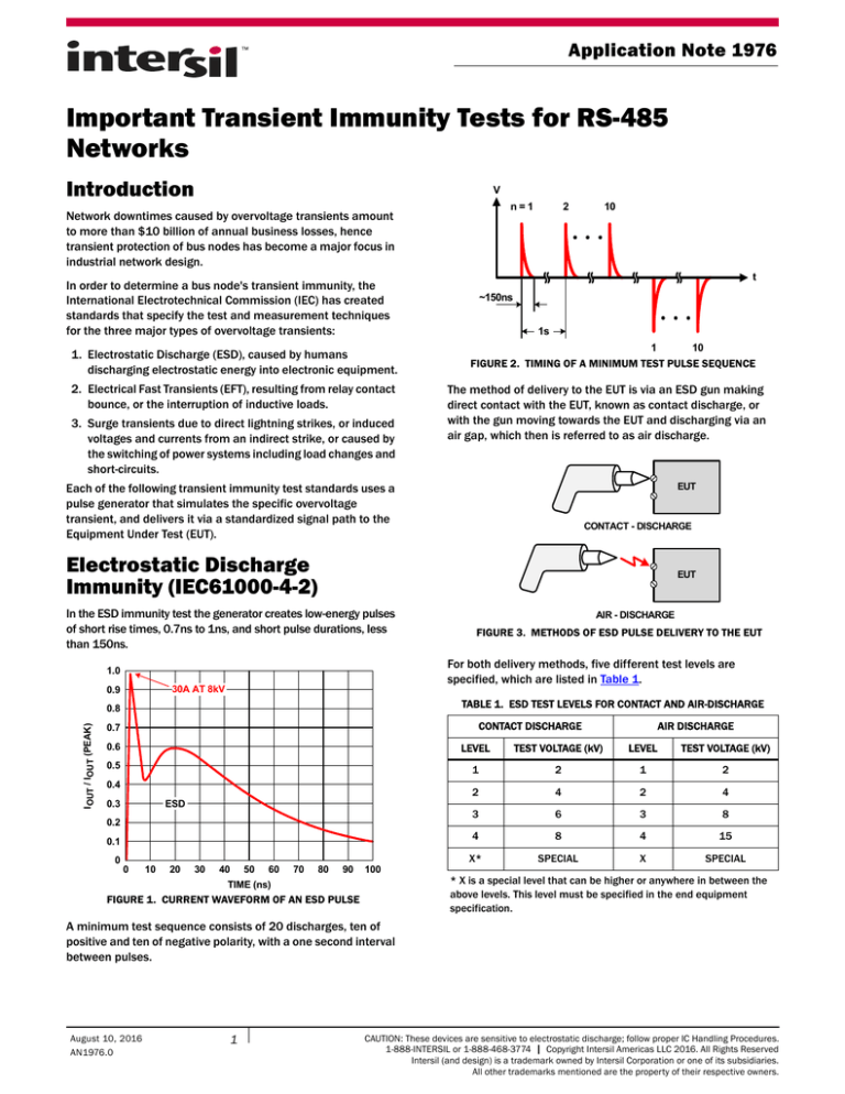
In the ESD immunity test the generator creates low-energy pulses
of short rise times, 0.7ns to 1ns, and short pulse durations, less
than 150ns.
30A AT 8kV
TABLE 1. ESD TEST LEVELS FOR CONTACT AND AIR-DISCHARGE
0.8
IOUT / IOUT (PEAK)
FIGURE 3. METHODS OF ESD PULSE DELIVERY TO THE EUT
For both delivery methods, five different test levels are
specified, which are listed in Table 1.
1.0
0.9
AIR - DISCHARGE
CONTACT DISCHARGE
0.7
AIR DISCHARGE
0.6
LEVEL
TEST VOLTAGE (kV)
LEVEL
TEST VOLTAGE (kV)
0.5
1
2
1
2
2
4
2
4
3
6
3
8
4
8
4
15
X*
SPECIAL
X
SPECIAL
0.4
0.3
ESD
0.2
0.1
0
0
10
20
30
40
50
60
70
80
90
100
TIME (ns)
FIGURE 1. CURRENT WAVEFORM OF AN ESD PULSE
* X is a special level that can be higher or anywhere in between the
above levels. This level must be specified in the end equipment
specification.
A minimum test sequence consists of 20 discharges, ten of
positive and ten of negative polarity, with a one second interval
between pulses.
August 10, 2016
AN1976.0
1
CAUTION: These devices are sensitive to electrostatic discharge; follow proper IC Handling Procedures.
1-888-INTERSIL or 1-888-468-3774 | Copyright Intersil Americas LLC 2016. All Rights Reserved
Intersil (and design) is a trademark owned by Intersil Corporation or one of its subsidiaries.
All other trademarks mentioned are the property of their respective owners.
Application Note 1976
Electrical Fast Transient
Immunity (IEC61000-4-4)
In the EFT immunity test the generator creates a sequence of
low-energy pulses known as a burst. Each pulse has a rise time of
5ns and a pulse duration of around 50ns (time-to-half value). The
burst period is 300ms and includes 75 transients followed by a
pause interval. For a pulse repetition rate of 5kHz the 75 pulses take
15ms, while for a repetition rate of 100kHz they take only 0.75ms.
While the individual pulse represents a low-energy transient, the
entire pulse train does not. For a given test voltage, the energy of
an EFT pulse train is some 250 times higher than the energy of a
single EFT pulse, as shown in Figure 10 on page 4.
The method of pulse delivery to the EUT is via a capacitive clamp
which surrounds the data or power lines of the EUT. The EFT test
therefore represents a common-mode test for differential mode
data lines.
1.0
CAPACITIVE
CLAMP
0.9
EUT
VOUT / VOUT (PEAK)
0.8
0.7
0.6
EFT
GEN.
0.5
0.4
0.3
FIGURE 6. METHOD OF EFT PULSE DELIVERY TO THE EUT
EFT
0.2
0.1
0
0
10
20
30
40
50
60
70
80
90
100
TIME (ns)
FIGURE 4. CURRENT WAVEFORM OF AN EFT PULSE
The minimum required test duration is two minutes. A typical
test sequence consists of three windows of ten seconds of
positive pulses, each followed by a 10 second pause interval, and
three ten second windows of negative pulses, with a 10 second
pause interval between pulses.
V
t
~400ns
Table 2 shows there are five test levels which differ in test voltage
severity for power and data lines. For the first four levels the test
voltage doubles with each level increment. The fifth level, X, is a
special level that can assume any test voltage. However, the
voltage level must be specified in the end equipment
manufacturer's specification.
TABLE 2. EFT TEST LEVELS FOR POWER AND DATA LINES
TEST VOLTAGE (kV)
LEVEL
REPETITION RATE
(kHz)
POWER PORTS
DATA LINES
1
5
0.5
0.25
2
1
0.5
3
2
1
4
4
2
SPECIAL
SPECIAL
X
SPECIAL
~200µs
V
Surge Immunity (IEC61000-4-5)
75 PULSES
AT 5kHz
t
15ms
300ms
V
1
2
In the surge immunity test, a combination waveform generator
(CWG) creates high-energy, low frequency test pulses whose
waveform is a combination of two separately defined waveforms:
an open-circuit voltage waveform and a short-circuit current
waveform.
The open-circuit voltage waveform has a rise time of 1.2µs and a
time to half-value of 50µs (often called a “1.2/50µs” pulse),
while the short-circuit current waveform has a rise time of 8µs
and a time to half-value of 20µs and is therefore referred to as an
"8/20µs" pulse.
6
t
10s
10s
FIGURE 5. TIMING OF A TYPICAL EFT TEST SEQUENCE
During a 10 second window, 33.3 bursts or 2500 pulses are
generated, thus resulting in a total of 15000 positive and 15000
negative pulses during a two minute test sequence.
Submit Document Feedback
2
AN1976.0
August 10, 2016
Application Note 1976
Table 3 shows there are five test levels which differ in test
voltage severity. For the first four levels the test voltage doubles
with each level increment. The fifth level, X, is a special level that
can assume any test voltage, but must be specified in the end
equipment manufacturer's specifications.
1.0
0.9
VOUT / VOUT (PEAK)
0.8
OPEN-CIRCUIT
VOLTAGE
0.7
0.6
TABLE 3. SURGE TEST LEVELS
0.5
0.4
SURGE
0.3
SHORT-CIRCUIT
CURRENT
0.2
0.1
0
0
10
20
30
40
50
TIME (µs)
60
70
80
LEVEL
TEST VOLTAGE (kV)
1
0.5
2
1
3
2
4
4
X
SPECIAL
FIGURE 7. VOLTAGE AND CURRENT WAVEFORMS OF A CWG
A test sequence requires 5 positive and 5 negative surge pulses
with a pause interval between successive pulses of one minute or
less. It is common procedure to shorten the pause intervals down
to 12 seconds, thus reducing the total test time below 2 minutes.
While this approach significantly reduces test time and cost, it
intensifies the surge impact due to the protection circuit's
reduced recovery time between pulses.
V
1
2
5
t
~200µs
TABLE 4. SURGE TEST VOLTAGE BY INSTALLATION CLASS
INSTALLATION CLASS
SYMMETRICAL LINES TEST VOLTAGE (kV)
0
NA
1
0.5
2
1
3
2
4
2
5
4
The standard defines the installation classes as follows:
• Class 0: Well-protected electrical environment
12s
1
5
FIGURE 8. TIMING OF A TYPICAL SURGE TEST PULSE SEQUENCE
The method of pulse delivery to the EUT is via resistive coupling
onto the balanced data lines of the EUT. For surge immunity tests
on symmetrical interconnections, IEC61000-4-5 specifies a
source impedance of 42Ω, which, in the case of RS-485, consists
of the 2Ω generator output resistance, defined by the ratio of
peak open-circuit output voltage to peak short-circuit output
current, and two 80Ω resistors of a Coupling/Decoupling
Network (CDN), each forming a separate signal path from the
CWG to the EUT data lines, shown in Figure 9.
2R
CWG
• Class 1: Partly protected electrical environment
• Class 2: Electrical environment where the cables are well
separated, even at short runs
• Class 3: Electrical environment where cables run in parallel
• Class 4: Electrical environment where the interconnections run
as outdoor cables along with power cables, and cables are
used for both electronic and electric circuits
• Class 5: Electrical environment for electronic equipment
connected to communication cables and overhead power lines
in a non-densely populated area
• Class X: Special conditions specified in the product
specification
80R
VT
For symmetrically operated data lines, such as RS-485,
IEC61000-4-5, specifies the test voltages by installation classes,
shown in Table 4.
EUT
80R
The combination of high currents, high voltages and long pulse
duration makes the surge test undoubtedly the most severe
amongst all transient immunity tests.
FIGURE 9. METHOD OF SURGE PULSE DELIVERY TO THE EUT
Submit Document Feedback
3
AN1976.0
August 10, 2016
Application Note 1976
Measurement results from test equipment manufacturers have
yielded the energy-versus-test voltage diagram in Figure 10.
1000
To successfully protect RS-485 networks against lethal surge
transients, semiconductor manufacturers offer transient voltage
suppressors capable of absorbing powers from a few hundred up
to several thousand watts. Their functionality and main features
are discussed in application note AN1977, “Transient Voltage
Suppressors: Operation and Features”.
100
SURGE
PULSE ENERGY (Joule)
10
1
It can be seen that for a given test voltage the energy content of a
surge pulse is around 100 times higher than that of an EFT pulse
train and more than 8-million times higher than the energy of an
ESD pulse!
EFT PULSE TRAIN
0.10
0.01
SINGLE EFT PULSE
10-3
10-4
ESD
10-5
10-6
0.5
1
2
4
6
8 10
15
PEAK PULSE VOLTAGE (kV)
FIGURE 10. COMPARISON OF PULSE ENERGIES FOR VARIOUS
TRANSIENT IMMUNITY TESTS
Intersil Corporation reserves the right to make changes in circuit design, software and/or specifications at any time without notice. Accordingly, the reader is
cautioned to verify that the document is current before proceeding.
For information regarding Intersil Corporation and its products, see www.intersil.com
Submit Document Feedback
4
AN1976.0
August 10, 2016


