Ordering Information
advertisement

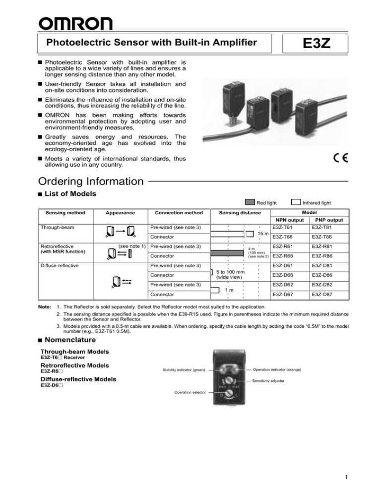
E3Z Photoelectric Sensor with Built-in Amplifier Photoelectric Sensor with built-in amplifier is applicable to a wide variety of lines and ensures a longer sensing distance than any other model. User-friendly Sensor takes all installation and on-site conditions into consideration. Eliminates the influence of installation and on-site conditions, thus increasing the reliability of the line. OMRON has been making efforts towards environmental protection by adopting user and environment-friendly measures. Greatly saves energy and resources. The economy-oriented age has evolved into the ecology-oriented age. Meets a variety of international standards, thus allowing use in any country. Ordering Information List of Models Red light Sensing Se s g method e od Appearance ppea a ce Connection Co ec o method e od Infrared light Model Sensing Se s gd distance s a ce NPN output Through-beam Pre-wired (see note 3) 15 m Connector Retroreflective (with MSR function) (see note 1) Pre-wired (see note 3) 4m (100 mm) (see note 2) Connector Diffuse-reflective Pre-wired (see note 3) 5 to 100 mm (wide view) Connector Pre-wired (see note 3) PNP output E3Z-T61 E3Z-T81 E3Z-T66 E3Z-T86 E3Z-R61 E3Z-R81 E3Z-R66 E3Z-R86 E3Z-D61 E3Z-D81 E3Z-D66 E3Z-D86 E3Z-D62 E3Z-D82 E3Z-D67 E3Z-D87 1m Connector Note: 1. The Reflector is sold separately. Select the Reflector model most suited to the application. 2. The sensing distance specified is possible when the E39-R1S used. Figure in parentheses indicate the minimum required distance between the Sensor and Reflector. 3. Models provided with a 0.5-m cable are available. When ordering, specify the cable length by adding the code “0.5M” to the model number (e.g., E3Z-T61 0.5M). Nomenclature Through-beam Models E3Z-T6j Receiver Retroreflective Models E3Z-R6j Stability indicator (green) Diffuse-reflective Models Operation indicator (orange) Sensitivity adjuster E3Z-D6j Operation selector 1 E3Z E3Z Accessories (Order Separately) Slit for Through-beam Models Slit width Sensing distance (typical) Minimum sensing object (typical) Model 0.5 mm dia. 50 mm 0.5 mm dia. E39-S65A 1 mm dia. 200 mm 1 mm dia. E39-S65B 2 mm dia. 800 mm 2 mm dia. E39-S65C 0.5 10 mm 1m 0.7 mm dia. E39-S65D 1 10 mm 2.2 m 1.2 mm dia. E39-S65E 2 10 mm 5m 2.4 mm dia. E39-S65F Quantity required O e eac One each for o the e emitter itt and d receiver. i Remarks These ese Slits S s are ae available il bl for f the th E3Z-Tjj E3Z-Tjj. Reflectors for Retroreflective Models Name Sensing distance (typical) Reflector e ec o Model Remarks 3 m (100 mm) E39-R1 4 m (100 mm) E39-R1S Retroreflective e o e ec e models ode s are a e not o id d with ith R fl t provided Reflectors. 5 m (100 mm) (see note 2) E39-R2 The MSR function is available. Miniature Reflector 1.5 m (50 mm) (see note 2) E39-R3 Tape a e Reflector e ec o 700 mm (150 mm) (see note 2) E39-RS1 1.1 m (150 mm) (see note 2) E39-RS2 1.4 m (150 mm) (see note 2) E39-RS3 Note: 1. Figure in parentheses indicates the minimum required distance between the Sensor and Reflector. 2. The actual sensing distance may be reduced to approximately 70% of the typical sensing distance when using a Reflector other than E39-R1 or E39-R1S. Mounting Brackets Appearance Model Appearance E39-L104 Model E39-L93 Remarks For Sensor adjustment use. Mounted to the aluminum frame rails of conveyors and adjustable with ease. E39-L43 E39-L98 E39-L44 Note: Vertical protective cover bracket If a through-beam model is used, order two Mounting Brackets for the emitter and receiver respectively. Sensor I/O Connectors Cable Standard Appearance Straight L-shaped 2 Cable type 2m Four-wire type Model XS3F-M421-402-A 5m XS3F-M421-405-A 2m XS3F-M422-402-A 5m XS3F-M422-405-A E3Z E3Z Specifications Ratings/Characteristics Item Sensing method Through-beam Retroreflective with MSR function NPN output E3Z-T61/T66 E3Z-R61/R66 E3Z-D61/D66 E3Z-D62/D67 PNP output (see note 3) E3Z-T81/T86 E3Z-R81/R86 E3Z-D81/D86 E3Z-D82/D87 Sensing distance 15 m 4 m (100 mm)* (when using E39-R1S) 3 m (100 mm)* (when using E39-R1) Opaque: 75-mm dia. min. Diffuse-reflective White paper (100 100 mm): 100 mm White paper (300 300 mm): 1m Standard sensing object Opaque: 12-mm dia. min. Hysteresis --- Directional angle Both emitter and receiver: 3 to 15° 2 to 10° --- Light source (wave length) Infrared LED (860 nm) Red LED (680 nm) Infrared LED (860 nm) Power supply voltage 12 to 24 VDC ±10% including 10% (p-p) max. ripple Current consumption Emitter: 15 mA Receiver: 20 mA Control output Load power supply voltage: 26.4 V max. Load current: 100 mA max. (Residual voltage: 1 V max.) Open collector output (NPN or PNP depending on model) L-ON/D-ON selectable Circuit protection Protection from load short-circuit and reversed power supply connection Response time Operation or reset: 1 ms max. Sensitivity adjustment One-turn adjuster Ambient illumination (receiver side) Incandescent lamp: 3,000 ȏx max. Sunlight: 10,000 ȏx max. Ambient temperature Operating: –25°C to 55°C/Storage: –40°C to 70°C (with no icing or condensation) Ambient humidity Operating: 35% to 85%/Storage: 35% to 95% (with no condensation) Insulation resistance 20 MΩ min. at 500 VDC Dielectric strength 1,000 VAC, 50/60 Hz for 1 min Vibration resistance 10 to 55 Hz, 1.5-mm double amplitude or 300 m/s2 for 2 hours each in X, Y, and Z directions Shock resistance Destruction: 500 m/s2 3 times each in X, Y, and Z directions Degree of protection IP67 (IEC60529) Connection method 500-mm-thick pre-wired cable (standard length: 2 m) with M8 connector Indicator Operation indicator (orange) Stability indicator (green) Emitter has power indicator (orange) only. 20% max. of setting distance 30 mA max. Protection from reversed power supply connection, output short-circuit, and mutual interference protection Weight (packed (p t t ) state) Pre-wired cable (2 m) Approx. 120 g Approx. 65 g Connector Approx. 30 g Approx. 20 g Material ae a Case PBT (polybutylene terephthalate) Lens Methacrylate resin Accessories Note: --- Instruction manual (The Reflector or Mounting Bracket is not provided with any of the above models.) *Figures in parentheses indicate the minimum required distances between the Sensors and Reflectors. 3 E3Z E3Z Engineering Data Parallel Operating Range (Typical) E3Z-Rj1 (Rj6) and Reflector Distance Y (mm) Retroreflective Models E3Z-Tj1 (Tj6) and Slit Distance Y (mm) Through-beam Models E3Z-Tj1 (Tj6) Distance Y (mm) Through-beam Models 2-dia. slit E39-RS3 E39-RS2 E39-RS1 Distance X (m) Distance X (m) 1-dia. slit Distance X (m) Slit: 1 x 10 Slit: 0.5 x 10 E39-R2 Slit: 2 x 10 E39-R3 E39-R1S E39-R1 Operating Range (Typical) E3Z-Dj2 (Dj7) Distance Y (mm) Diffuse-reflective Models E3Z-Dj1 (Dj6) Distance Y (mm) Diffuse-reflective Models Black carbon Distance X (m) Distance X (mm) Black carbon White drawing paper 4 SUS (glossy surface) White drawing paper SUS (glossy surface) E3Z E3Z Excess Gain Ratio vs. Distance (Typical) E3Z-Dj1 (Dj6) Operating level Excess gain ratio Diffuse-reflective Models E3Z-Rj1 (Rj6) and Reflector Excess gain ratio Retroreflective Models E3Z-Tj1 (Tj6) Excess gain ratio Through-beam Models E39-R2 Operating level Sensing object: 100 x 100 mm white paper Operating level E39-R3 E39-R1S E39-R1 Distance X (m) Distance X (m) Distance X (mm) Diffuse-reflective Model E3Z-Dj2 (Dj7) Excess gain ratio Sensing object: 300 x 300 mm white paper Operating level Distance X (m) Sensing Object Size vs. Sensing Distance (Typical) Diffuse-reflective Models E3Z-Dj1 (Dj6) E3Z-Dj2 (Dj7) White paper SUS (glossy surface) Distance (m) Distance (mm) Diffuse-reflective Models SUS (glossy surface) White paper Black paper Side length (one side) of sensing object: d (mm) Black paper Side length (one side) of sensing object: d (mm) 5 E3Z E3Z Operation NPN Output Model E3Z-T61/-T66/-R61/-R66/-D61/-D66/-D62/-D67 Output transistor status Light ON Timing chart Incident Interrupted Operation indicator (orange) ON OFF Output transistor ON Incident Interrupted Operation indicator (orange) ON OFF OFF Operate Reset (Between brown and black) (Between brown and black) Mode selector Light ON (L/ON) Output circuit Through-beam receiver 12 to 24 VDC Diffuse-reflective model Brown Green 100 mA Black max. Control output Blue 12 to 24 VDC Stability indicator Orange Main circuit Dark ON (D/ON) Retroreflective model Operation indicator Brown OFF Load (relay) Reset Power indicator (orange) ON Output transistor Operate Load (relay) Through-beam emitter Dark ON Load (Relay) Connector Pin Arrangement Main circuit Blue Pins 2, 4 are open. 0V Connector Pin Arrangement Pin 2 is open. PNP Output Model E3Z-T81/-T86/-R81/-R86/-D81/-D86/-D82/-D87 Output transistor status Light ON Timing chart Incident Interrupted Operation indicator (orange) ON OFF Output transistor ON Load (relay) Through-beam emitter Dark ON Incident Interrupted Operation indicator (orange) ON OFF Output transistor OFF Operate Operate Reset (Between blue and black) (Between blue and black) Mode selector Light ON (L/ON) Output circuit Through-beam receiver Brown OFF Load (relay) Reset Power indicator (orange) ON Main circuit Dark ON (D/ON) Retroreflective model 12 to 24 VDC Diffuse-reflective model Blue Brown Operation indicator Orange 12 to 24 VDC Stability indicator Green Connector Pin Arrangement Black Main circuit Control output 100 mA max. Blue Load (Relay) Pins 2, 4 are open. 0V Connector Pin Arrangement Pin 2 is open. Structure of Sensor I/O Connector Wire colors Brown White Blue Black XS3F-M421-402-A XS3F-M421-405-A XS3F-M422-402-A XS3F-M422-405-A 6 Classification DC Wire color Brown Connector pin No. A Use Power supply (+V) White B Blue C Power supply (0 V) Black D Output --- E3Z E3Z Note: Pin 2 is not used. Dimensions Note: All units are in millimeters unless otherwise indicated. Sensors Through-beam (Pre-wired Models) Through-beam (Connector Models) E3Z-T61 E3Z-T81 E3Z-T66 E3Z-T86 Emitter Emitter Power indicator (orange) Power indicator (orange) Lens Lens Optical axis Optical axis Two, M3 Two, M3 Vinyl-insulated round cable with two conductors, 4 dia. (0.2 mm2 with 1.1-dia. insulator); standard length: 2m M8 connector Power indicator (orange) Power indicator (orange) Receiver Stability indicator (green) Operation selector Sensing adjuster Lens Receiver Operation selector Sensing adjuster Lens Optical axis Optical axis Stability indicator (green) Two, M3 Two, M3 Vinyl-insulated round cable with three conductors, 4 dia. (0.2 mm2 with 1.1-dia. insulator); standard length: 2m M8 connector Retroreflective Models (Pre-wired Models) Retroreflective Models (Connector Models) E3Z-R61 E3Z-R81 E3Z-R66 E3Z-R86 Diffuse-reflective Models Diffuse-reflective Models E3Z-D61 E3Z-D62 E3Z-D81 E3Z-D82 E3Z-D66 E3Z-D67 E3Z-D86 E3Z-D87 Power indicator (orange) Operation selector Stability indicator Sensing adjuster (green) Two, 7-dia. lenses Receiver Optical axis Emitter Two, M3 Vinyl-insulated round cable with three conductors, 4 dia. (0.2 mm2 with 1.1-dia. insulator); standard length: 2m Power indicator (orange) Stability indicator (green) Operation selector Sensing adjuster Two, 7-dia. lenses Receiver Optical axis Emitter Two, M3 M8 connector 7 E3Z E3Z Accessories (Order Separately) Slits E39-S65D E39-S65E E39-S65F E39-S65A E39-S65B E39-S65C Model E39-S65A E39-S65B E39-S65C Side A 0.5 dia. 1.0 dia. 2.0 dia. Reflectors E39-R1 E39-R1S Material Model SUS301 stainless steel E39-S65D E39-S65E E39-S65F Side A 0.5 1.0 2.0 Material SUS301 stainless steel Miniature Reflector E39-R3 Two, 3.5 dia. Material Surface: Acrylic resin Backside: ABS resin Material Surface: Acrylic resin Backside: ABS resin Adhesive tape side Two, 3.2 dia. E39-R2 Four, 3.5 dia. Two, M3 SUS304 stainless steel Material Surface: Acrylic resin Backside: ABS resin 8 E3Z E3Z Tape Reflectors E39-RS3 E39-RS1 Adhesive tape side Material: Acrylic resin E39-RS2 Adhesive tape side Material: Acrylic resin Adhesive tape side Material: Acrylic resin Mounting Brackets E39-L104 With Mounting Bracket (E3Z-D62) Two, 3.2 dia. Optical axis Two, M3 Material: SUS304 stainless steel E39-L43 With Mounting Bracket (E3Z-D62) Two, M3 Four, 3.2 dia. Optical axis Material: SUS304 stainless steel 9 E3Z E3Z E39-L44 With Mounting Bracket (E3Z-D62) Two, M3 Optical axis 3.2 dia. Material: SUS304 stainless steel E39-L93 Heat-resistive ABS resin Screw provided Heat-resistive ABS resin 3.2 dia. Twelve, 3.2 dia. SUS304 stainless steel 12 dia. SUS304 stainless steel Polybutylene terephthalate resin Four, 6.5 dia. E39-L98 Mounting Dimensions Two, M6 56 dia. Screw provided Material: SUS304 stainless steel 10 E3Z E3Z Sensor I/O Connectors Straight XS3F-M421-402-A (L=2 m) XS3F-M421-405-A (L=5 m) 4 dia. 9 dia. L-shaped XS3F-M422-402-A (L=2 m) XS3F-M422-405-A (L=5 m) 4 dia. Precautions Be sure to abide by the following precautions for the safe operation of the Sensor. Wiring Wiring Mistakes Do not make mistakes in wiring, such as mistakes in polarity, otherwise the Sensor may be damaged. Power Supply Voltage Make sure that the power supply to the Sensor is within the rated voltage range and do not apply 100 VAC or more if the Sensor is a DC model, or otherwise the Sensor may explode or burn. Connection without Load Do not connect power supply to the Sensor with no load connected, otherwise the internal elements may explode or burn. Load Short-circuiting Do not short-circuit the load, otherwise the Sensor may be damaged. Do not use the Sensor in locations with explosive or flammable gas. Operating Environment Correct Use Settings Mounting Power Reset Time The Sensor is ready to operate 100 ms after the Sensor is turned ON. If the load and Sensor are connected to independent power supplies respectively, be sure to turn ON the Sensor before turning the load ON. Sensor Mounting Use M3 screws to mount the sensor and tighten each screw to a maximum torque of 0.53 N S m. Connections M8 Metal Connector • • • • Be sure to connect or disconnect the metal connector after turning OFF the Sensor. Hold the connector cover to connect or disconnect the metal connector. Secure the connector cover by hand. Do not use any pliers, otherwise the connector may be damaged. E3Z-jjj E39-L104 Mounting Bracket (sold separately) The proper tightening torque range is between 0.3 and 0.4 N S m. Be sure to tighten the connector securely, otherwise the specified degree of protection may not be maintained or the connector may be disconnected due to vibration. 11 E3Z E3Z Adjustment Slits for Through-beam Models (E39-S65A/B/C/D/E/F (Sold Separately)) Slit Sensor Hook Upper indented mounting portion Protruding portion Slit Lower mounting dent portion Sensor Mounting method 1. Hook the upper protruding portion of the Slit to the upper indented mounting portion of the Sensor and adjust the position of the Slit so that the Slit will be in parallel to the lens side of the Sensor. 2. Press the lower protruding portion of the Slit onto the indented mounting portion of the Sensor until the Slit snaps in. Side view Mounting condition Front view Removal method 1. Press the upper portion of the Slit. 2. Disconnect the lower protruding portion of the Slit from the Sensor and remove the Slit. ALL DIMENSIONS SHOWN ARE IN MILLIMETERS. To convert millimeters into inches, multiply by 0.03937. To convert grams into ounces, multiply by 0.03527. Cat. No. E308-E1-1 In the interest of product improvement, specifications are subject to change without notice. OMRON Corporation Industrial Automation Company Industrial Sensors Division Sensing Devices and Components Division H.Q. 28th Fl., Crystal Tower Bldg., 1-2-27, Shiromi, Chuo-ku, Osaka 540-6028 Japan Phone: (81)6-6949-6012 Fax: (81)6-6949-6021 12 Printed in Japan 0799-5M (0799) a


