Technical Specifications
advertisement

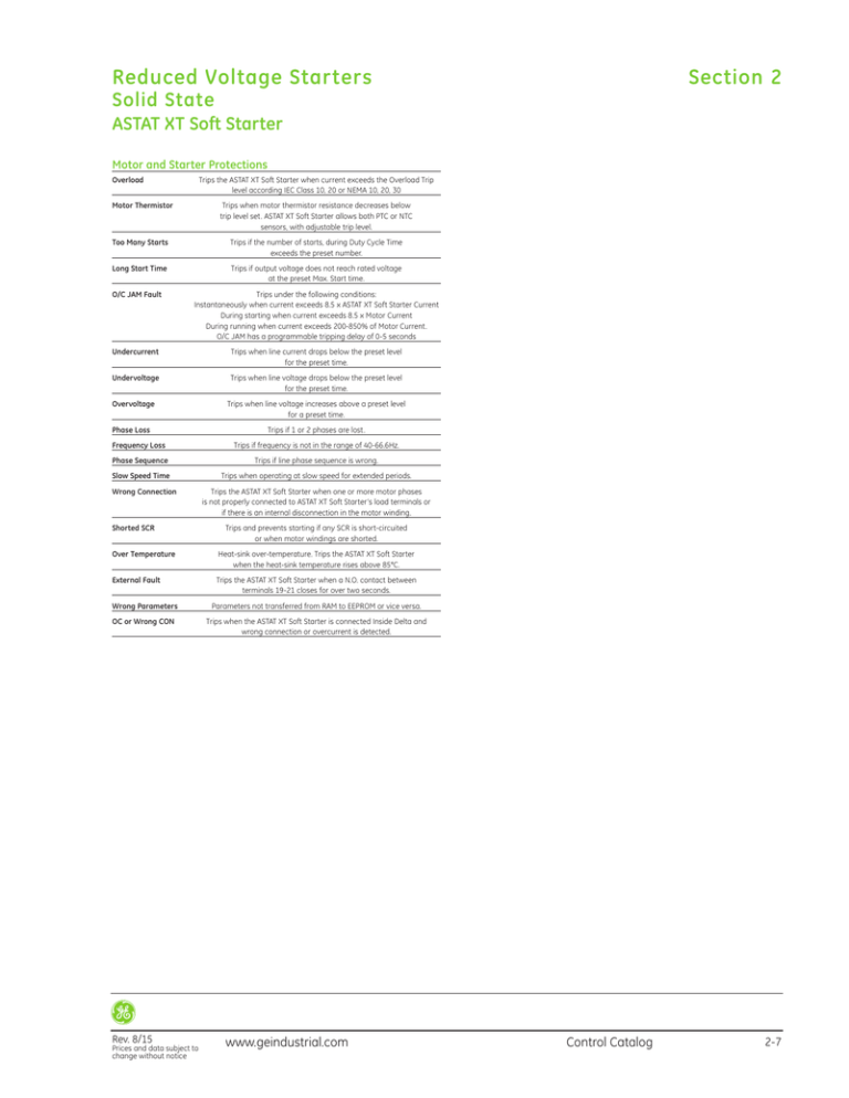
Reduced Voltage Starters Section 2 Solid State ASTAT XT Soft Starter Motor and Starter Protections Overload Trips the ASTAT XT Soft Starter when current exceeds the Overload Trip level according IEC Class 10, 20 or NEMA 10, 20, 30 Motor Thermistor Trips when motor thermistor resistance decreases below trip level set. ASTAT XT Soft Starter allows both PTC or NTC sensors, with adjustable trip level. Too Many Starts Trips if the number of starts, during Duty Cycle Time exceeds the preset number. Long Start Time Trips if output voltage does not reach rated voltage at the preset Max. Start time. O/C JAM Fault Trips under the following conditions: Instantaneously when current exceeds 8.5 x ASTAT XT Soft Starter Current During starting when current exceeds 8.5 x Motor Current During running when current exceeds 200-850% of Motor Current. O/C JAM has a programmable tripping delay of 0-5 seconds Undercurrent Trips when line current drops below the preset level for the preset time. Undervoltage Trips when line voltage drops below the preset level for the preset time. Overvoltage Trips when line voltage increases above a preset level for a preset time. Phase Loss Frequency Loss Trips if 1 or 2 phases are lost. Trips if frequency is not in the range of 40-66.6Hz. Phase Sequence Trips if line phase sequence is wrong. Slow Speed Time Trips when operating at slow speed for extended periods. Wrong Connection Shorted SCR Trips the ASTAT XT Soft Starter when one or more motor phases is not properly connected to ASTAT XT Soft Starter’s load terminals or if there is an internal disconnection in the motor winding. Trips and prevents starting if any SCR is short-circuited or when motor windings are shorted. Over Temperature Heat-sink over-temperature. Trips the ASTAT XT Soft Starter when the heat-sink temperature rises above 85°C. External Fault Trips the ASTAT XT Soft Starter when a N.O. contact between terminals 19-21 closes for over two seconds. Wrong Parameters Parameters not transferred from RAM to EEPROM or vice versa. OC or Wrong CON Trips when the ASTAT XT Soft Starter is connected Inside Delta and wrong connection or overcurrent is detected. Rev. 8/15 Prices and data subject to change without notice www.geindustrial.com Control Catalog 2-7 Section 2 Reduced Voltage Starters Solid State ASTAT XT Soft Starter Functions Standard Functions Soft Start and Soft Stop ASTAT XT Soft Starter is provided with soft start and soft stop features, including five independent acceleration and deceleration curve models. The factory default curve is used for general purpose; three are used for pump control and one for torque control. Pump Control Specific function for pump control, that avoids overpressure in the system at the end of acceleration phase and suppresses the hammering at stopping phase Torque Control Provides a smooth time controlled torque ramp acceleration and deceleration, with linear deceleration of the torque resulting in a close to linear speed deceleration, thus eliminating stall conditions. In Line / Inside Delta ASTAT XT Soft Starter allows either traditional Line operation or Inside Delta operation. When the ASTAT XT Soft Starter is installed to operate Inside Delta, the individual phases of the starter are connected in series with the individual motor windings (six wiring connections like the Start-Delta starters), thus reducing the current x1.73, and allowing the use of a much smaller starter (x1.5 less than motor rated current) Bypass ASTAT XT Soft Starter allows bypass operation using an external contactor, controlled ON/OFF by starter function EOR (End Of Ramp). The starter is provided with three dedicated power terminals to facilitate wiring to the bypass contactor. ASTAT XT Soft Starter protections to motor are enabled, even in bypass All ASTAT XT Soft Starter models rated 950A and up must be operated with a bypass contactor. Kick Start This function allows the start of high friction loads that require high starting torque for a short period of time. When this function is enabled, a pulse of 80% Un during an adjustable time from 0 to 1sec is given to the motor. After this pulse the output voltage ramps down to Starting Voltage setting, before ramping up again to full voltage. End of Ramp Detects end of acceleration and outputs a signal by a dry relay contact. This signal can be delayed by an adjustable timer from 0-120 sec. Lock-Out Allows control of the number of starts in a period of time, protecting both motor and ASTAT. 2-6 Control Catalog Dual Settings By this function, ASTAT XT Soft Starter is able to control a secondary motor. Dual setting of Starting Voltage, Starting Current, Current Limit, Ramp Up, Ramp Down and Motor current parameters can be selected by using one of the programmable ASTAT XT Soft Starter’s inputs. Energy Saving Activated when the motor has a light load for extended periods of time, reducing the output voltage level and decreasing the reactive current and motor copper/Iron losses. This function can be enabled or disabled by dedicated parameters in ASTAT XT Soft Starter. Slow Speed Function that allows the motor to run at 1/6 constant rated speed, for a short period of time, maximum 30sec. This function supports forward and reverse operation. Auto Reset This function allows the ASTAT XT Soft Starter to automatically recover after a fault caused by Undervoltage, Undercurrent or Phase lost. Auto-Reset can be programmed up to maximum 10 attempts. Cooling Fan Control Allows three methods of control for the ASTAT’s built-in cooling fans: - Continuous Operation - Controlled by an external input - Automatically OFF controlled; after five minutes ASTAT XT Soft Starter is stopped Generator Supply This is a specific function useful when the Starter is powered from a diesel generator rather than from a commercial power supply. The function is enabled by an internal dip switch, and helps to minimize the negative effects caused by the generator’s voltage fluctuations during starting. Keypad Lock This function is enabled by means of starter’s internal dip switch, locking the keypad. This is useful to prevent undesired parameter modifications. Built-In Communications ASTAT XT Soft Starter includes a ModBus RTU communications protocol. Communications are carried out through a half duplex RS485 port, with maximum baudrate of 9600, supporting up to 247 stations. Statistical Data ASTAT XT Soft Starter records useful data for maintenance and start up - Last 10 trip events - Number of starts, number of trip events and elapsed RUN time. - Last trip data information of motor current, starting current and acceleration time. www.geindustrial.com Rev. 8/15 Prices and data subject to change without notice Section 2 Reduced Voltage Starters Solid State ASTAT XT Soft Starter Technical Specifications I/O Terminal Board Specifications Power I/O Terminals Terminal Function Description 1L1, 3L2, 5L3 Mains Input 2T1, 4T2, 6T3 A, B, C G Output to motor Bypass Ground 3ph Input voltage according ASTAT XT Soft Starter Main Voltage Option rating (Option 1) 230-500VAC, +10%/-15% 50/60Hz (Option 2) 460-600VAC, +10%/-15% 50/60Hz (Option 3) 690VAC, +10%/-15% 50/60Hz Power Output terminals to 3ph AC motor Bypass terminals for external bypass contactor ASTAT XT Soft Starter, ground connection Terminal Function Description L, N F Control. Supply Fan Control 110VAC or 220VAC, according ASTAT XT Soft Starter Control Voltage rating Cooling fan external control, together with jumper J1 Control Power Supply Control Voltage & Fan consumption VA: QTx0008 to QTx0031: No fan. Total consumption: 150VA QTx0044 to QTx0072: Fan 35 VA. Total consumption 185VA QTx0085 to QTx0170: Fan 60 VA. Total consumption 210VA QTx0210 to QTx0390: Fans 105VA. Total consumption 255VA QTx0390 to QTx 1400A : Fans 150VA.Total consumption 300VA Digital Inputs Terminal Function Description 4 5 6 7 8 9 Stop Soft Stop Start Progamable Inputs Progamable Inputs Common Dedicated input to Stop Dedicated input to Soft Stop Dedicated input to Start Programmable to functions Energy Saving, Slow Speed and Reset Programmable to functions Dual Set, Reverse and Reset Common terminal for digital inputs from 4, 5, 6, 7 and 8 Operating Voltage of digital inputs from 4 to 9 Digital Input hardware is operated according either of below ordered voltage ratings (Option 1, standard) From 90 to 230VAC +10%, 50/60Hz (Option 2, Optional) 24VDC +10%/ -15% Other Inputs Terminal Function Description 19, 21 21 28, 29 External Fault Neutral Motor Thermistor Requires a free voltage relay contact, to detect external fault This terminal may be connected to Mains Neutral when available PTC or NTC programable input for motor thermistor protection The input can be enabled or disabled, and programmed at desired trip level resistance Terminal Function Description 10, 11, 12 13, 14, 15 16, 17, 18 RUN FAULT EOR Run Relay with NO & NC dry contact. Programmable ON delay Fault to ON or Fault to OFF programmable function End Of Ramp relay. Programmable ON delay Relay Outputs Ratings Max rating: 8A, 250VAC, 2000VA max Terminal Function Description 31, 32 30 Current Output Ground Range 0 to 2xIn. Programmable 0-10VDC, 0-20mA or 4-20mA. Ground terminal for Analog Output Terminal Function Description D+, D-, SG RS485 terminals D-9 connector V+, CL, Dr, CH, V- Profibus Port DeviceNet terminals RS485 Communication port, half duplex for ModBus protocol Baudrate 1200, 2400, 4800, 9600 BPS Optional Profibus Communications port Optional DeviceNet Communications port 2-10 Control Catalog Digital Outputs Analog Output Communications www.geindustrial.com Rev. 8/15 Prices and data subject to change without notice


