Quiz 3 PRACTICE : Passive frequency
advertisement

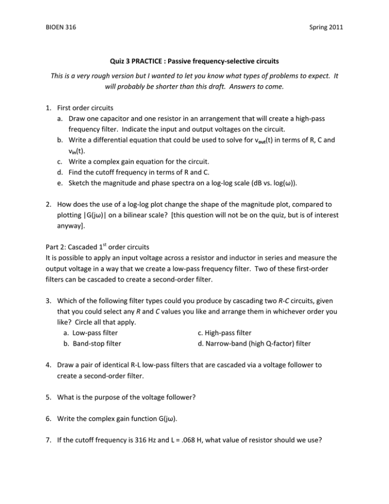
BIOEN 316 Spring 2011 Quiz 3 PRACTICE : Passive frequency‐selective circuits This is a very rough version but I wanted to let you know what types of problems to expect. It will probably be shorter than this draft. Answers to come. 1. First order circuits a. Draw one capacitor and one resistor in an arrangement that will create a high‐pass frequency filter. Indicate the input and output voltages on the circuit. b. Write a differential equation that could be used to solve for vout(t) in terms of R, C and vin(t). c. Write a complex gain equation for the circuit. d. Find the cutoff frequency in terms of R and C. e. Sketch the magnitude and phase spectra on a log‐log scale (dB vs. log(ω)). 2. How does the use of a log‐log plot change the shape of the magnitude plot, compared to plotting |G(jω)| on a bilinear scale? [this question will not be on the quiz, but is of interest anyway]. Part 2: Cascaded 1st order circuits It is possible to apply an input voltage across a resistor and inductor in series and measure the output voltage in a way that we create a low‐pass frequency filter. Two of these first‐order filters can be cascaded to create a second‐order filter. 3. Which of the following filter types could you produce by cascading two R‐C circuits, given that you could select any R and C values you like and arrange them in whichever order you like? Circle all that apply. a. Low‐pass filter c. High‐pass filter b. Band‐stop filter d. Narrow‐band (high Q‐factor) filter 4. Draw a pair of identical R‐L low‐pass filters that are cascaded via a voltage follower to create a second‐order filter. 5. What is the purpose of the voltage follower? 6. Write the complex gain function G(jω). 7. If the cutoff frequency is 316 Hz and L = .068 H, what value of resistor should we use? BIOEN 316 Spring 2011 8. What is the magnitude of G(jω) at the cutoff frequency, both on a linear scale and in dB? 9. How fast does |G(jω)| roll off as ω→∞? 10. Could we create a filter circuit with a high Q‐factor resonant peak by replacing one of the inductors with a capacitor? 11. Which of the following phrases best describes the relationship between the two filter stages? a. Multiplication in time, convolution in frequency b. Convolution in time, multiplication in frequency c. Addition in frequency, subtraction in time d. Multiplication in time and frequency 12. Given our cascaded R‐L circuits, what is an effect of replacing the voltage follower with a simple wire? a. It creates a resonant circuit b. It changes a LPF to a HPF c. It creates a second‐order circuit that does not resonate d. It increases the input impedance, Vin/Iin RLC circuits 13. Arrange R, L and C components in series to create a passive, second‐order band reject filter. Indicate the input and output voltage terminals. 14. Write the complex gain equation G(jω). 15. Assume that R = 1 kΩ, C = 330 nF, and L = 0.2 H. Is this a resonant circuit? 16. What is the range of R that produces resonance? 17. Sketch the phase and magnitude plots on a dB vs. log(ω) scale, indicating the three break frequencies.


