TH8061
Application Note
Application Hits for Selection of Output Capacitor
1.
Introduction
The voltage regulator of TH8061 is a low drop regulator (LDO) with a p-FET pass transistor.
This kind of regulator has a basic pole, which is caused from the internal frequency compensation.
An additional pole is dependent from the load resistor and the load capacity. This additional pole
caused in an instable behaviour of the regulator.
To compensate this pole it must be inserted a zero. This must be done via an external resistor in
series with a load capacity. For this compensation it is used the equivalent series resistance (ESR)
of the load capacity. This ESR resistor value is a characteristic of every real capacity and
generates a zero within the loop amplification and therefore it compensates the impact of the
negative phase shift.
The conclusion is that the regulator only shows stable behaviour within the defined limits for load
resistance RL and load capacity CL including a valid ESR range. The range of load resistance is
defined by the application and therefore the compensation can only be done via adjusting CL and
ESR.
2.
Load Capcitor Selection
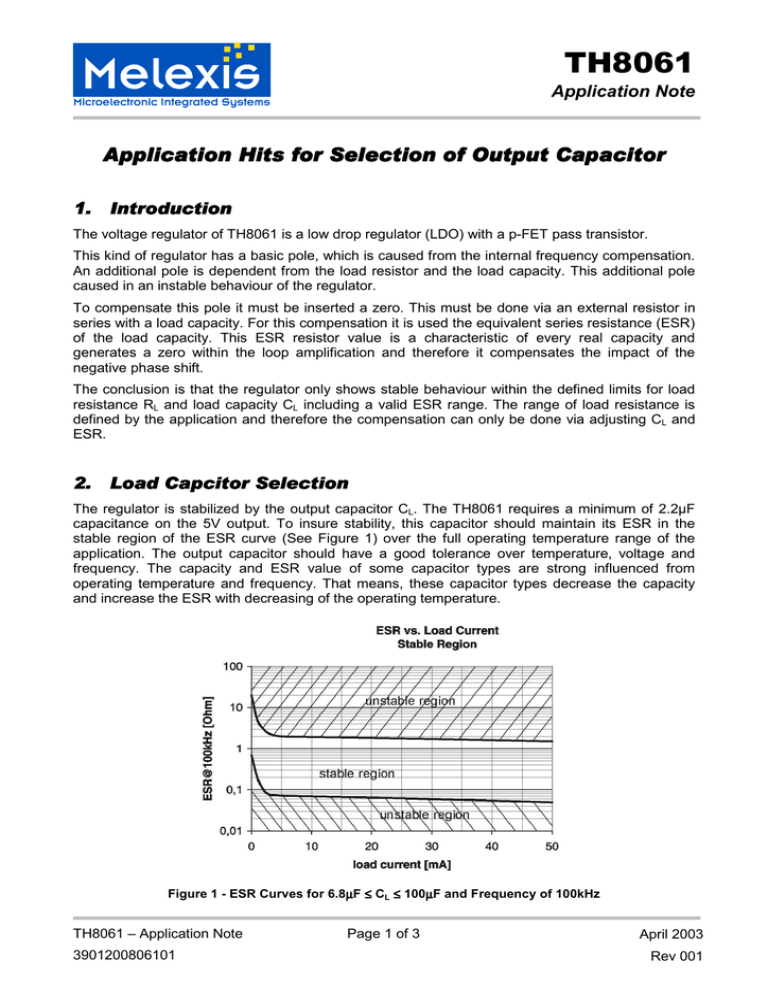
The regulator is stabilized by the output capacitor CL. The TH8061 requires a minimum of 2.2µF
capacitance on the 5V output. To insure stability, this capacitor should maintain its ESR in the
stable region of the ESR curve (See Figure 1) over the full operating temperature range of the
application. The output capacitor should have a good tolerance over temperature, voltage and
frequency. The capacity and ESR value of some capacitor types are strong influenced from
operating temperature and frequency. That means, these capacitor types decrease the capacity
and increase the ESR with decreasing of the operating temperature.
Figure 1 - ESR Curves for 6.8µ
µF ≤ CL ≤ 100µ
µF and Frequency of 100kHz
TH8061 – Application Note
3901200806101
Page 1 of 3
April 2003
Rev 001
TH8061
Application Note
The value and type of the output capacitor can be selected using the diagram shown in Figure 1.
The following two examples shows the effect of the stabilisation circuit using different values for the
output capacitor.
Example 1:
The regulator is stabilized using an aluminum electrolytic capacitor of 47µF (ESR=0.7Ω @ 25°C).
At Tamb=-40°C the capacitor value is decreased to 42µF and the ESR is increased to 8.9Ω. The
ESR value is located in the instable region of Figure 1. The regulator will be instable at a
temperature of Tamb=-40°C.
Example 2:
The regulator is stabilized using a tantalum capacitor of 47µF (ESR=0.1Ω @ 25°C). At Tamb=-40°C
the capacitor value is decreased to 45µF and the ESR is increased to 0.11Ω. The ESR value is
located in the stable region of Figure 1. The regulator will remain stable at a temperature of
Tamb=-40°C.
Melexis recommends the using of tantalum capacitors as VCC load capacitor for stable behaviour
of the TH8061-regulator. These types of capacitors shows a low change of the capacity and ESR
value over the whole automotive temperature range and therefore it fits to the requirements for low
drop regulators.
TH8061 – Application Note
3901200806101
Page 2 of 3
April 2003
Rev 001
TH8061
Application Note
Your notes
Important Notice
Devices sold by Melexis are covered by the warranty and patent indemnification provisions appearing in its Term of Sale. Melexis
makes no warranty, express, statutory, implied, or by description regarding the information set forth herein or regarding the freedom of
the described devices from patent infringement. Melexis reserves the right to change specifications and prices at any time and without
notice. Therefore, prior to designing this product into a system, it is necessary to check with Melexis for current information. This product
is intended for use in normal commercial applications. Applications requiring extended temperature range, unusual environmental
requirements, or high reliability applications, such as military, medical life-support or life-sustaining equipment are specifically not
recommended without additional processing by Melexis for each application.
The information furnished by Melexis is believed to be correct and accurate. However, Melexis shall not be liable to recipient or any third
party for any damages, including but not limited to personal injury, property damage, loss of profits, loss of use, interrupt of business or
indirect, special incidental or consequential damages, of any kind, in connection with or arising out of the furnishing, performance or use
of the technical data herein. No obligation or liability to recipient or any third party shall arise or flow out of Melexis’ rendering of
technical or other services.
© 2000 Melexis NV. All rights reserved.
For the latest version of this document. Go to our website at
www.melexis.com
Or for additional information contact Melexis Direct:
Europe and Japan:
All other locations:
Phone: +32 1367 0795
E-mail: sales_europe@melexis.com
Phone: +1 603 223 2362
E-mail: sales_usa@melexis.com
QS9000, VDA6.1 and ISO14001 Certified
TH8061 – Application Note
3901200806101
Page 3 of 3
April 2003
Rev 001

