Volume-4, Issue-2, April-2014, ISSN No.: 2250-0758
International Journal of Engineering and Management Research
Available at: www.ijemr.net
Page Number: 176-180
Defects in Wheels and Axles and Detection by Ust
Lalit Kishor Mudgal1, Rakesh Kumar Sharma2, M.P. Singh3
M.Tech Scholar, Jagannath University, Jaipur, Rajasthan, INDIA
3
Associate Professor, Jagannath University, Jaipur, Rajasthan, INDIA
1,2
ABSTRACT
In this paper we discussed about various defects in the
wheel and axle of the locomotive and the techniques which
are currently employing in the Indian railway’s workshops
all over india. The techniques used are homogeneous
throughput the country which is designed and developed by
the RDSO, lucknow.
I.
WHEEL
Wheels are made up of carbon steel forgings which
are subsequently heat treated and machined to subsequent
dimensions. Wheels are also manufactured by casting
process. The defects in wheel may be classified in two
groups,
1. Inherent defects
2. Service defects
1. INHERENT DEFECTS
The defects encountered during steel-making ,
shaping and machining operations may be summarized as
unsatisfactory chemical composition, micro structure,
harmful inclusion, segregation, pipe, flake, etc. which are
associated with faults in the making of steel and
manufacturing into wheels.
As wheels are also manufactured by casting
process, defects related to casting may appear as porosity,
blowholes, and slag inclusions etc. Improper heat
treatment may lead to coarse grain structure, Processing
defect arise during machining, fabrication, handling etc.
They can be summarized as deep tool mark, dent mark
arising during machining, fabrication, handling etc.
2. SERVICE DEFECTS
Defects developing in wheels during their service
life due to service condition leading to failure . The
examples are written below.
2.1 Wheel shelling defect: Wheel shelling, separation of
metal from wheel , is a rolling contact fatigue phenomenon
that leads to damage on the wheel tread and eventually
small pieces of the wheel tread break off.
2.2 Thermal cracking defect: Thermal cracking is a
process that requires elevated temperatures which is
generated during severe braking. Often, these cracks are
found on wheels with heat checks and the cracks appear to
be closely related.
2.3 Sliding defect: It occurs when wheel will slide on a rail
as a result of the retarding force between wheel and brake
shoe is greater than the adhesive force between wheel and
rail.
2.4 Wheel Spalling defect: It occurs in service after the
wheel slides on the rail and patches of martensite are
formed on the tread. In spalling, the crack network is either
perpendicular or parallel to the surface.
2.5 Shattered Rim defect: This type of defect originate at
the sub-surface of tread resulting in fatigue initiation
which further progresses circumferentially and when the
fatigue crack gets connected with tread surface, a chunk of
metal is dislodged from tread.
Other defects in wheel can be written as sharp
corner at rim edge, wheel flat, spread rim, thinning of
flange, punch mark at wheel rim etc.
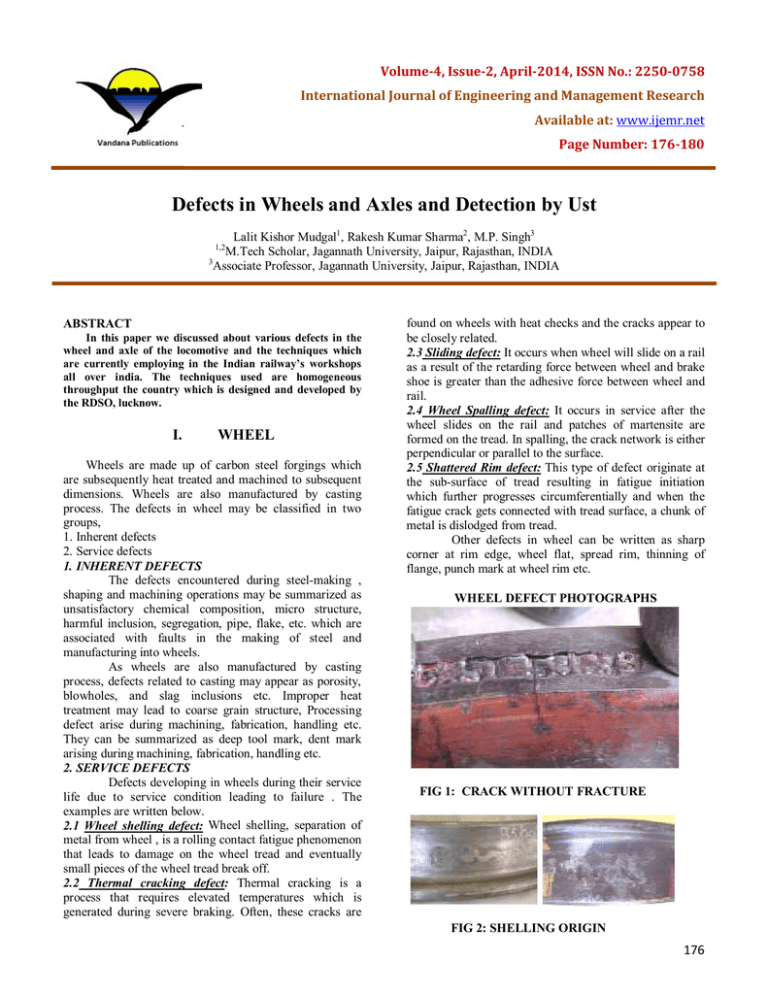
WHEEL DEFECT PHOTOGRAPHS
FIG 1: CRACK WITHOUT FRACTURE
FIG 2: SHELLING ORIGIN
176
(I) SURFACE MARTENSITE SPOTS,
NORMALLY BY SLIP
THERMAL DAMAGE TO WHEEL
(II) SUBSURFACE FATIGUE DUE TO ROLLING
CONTACT CAUSED BY TANGENTIAL STRESS
FIG 7: OBSERVATION ON HEATED WHEEL
Chemistry & Mechanical properties satisfactory
Macro showed heat affected area
Micro showed spheroidal pearlite
FIG 3: VERTICAL SPLIT
ORIGIN- INHERENT DEFECT IN INGOT
REMEDY- PROPER CROPPING OF INGOT
FIG 4: SHARP CORNER AT RIM EDGE
ORIGIN-SHARP CORNER AT RIM EDGE
REMEDY-AVOIDANCE OF SHARP EDGES
FIG 8: THERMAL DAMAGE TO WHEEL
FIG 5: SHATTERED RIM
ORIGIN- INHERENT DEFECT LIKE CLUSTER OF
INCLUSIONS,
FORGING
BURST,
LOWER
STRENGTH.
REMEDY- CLEAN STEEL, USFD - TREAD
PROBING
FIG 6: THERMAL CRACKS
ORIGIN-THERMAL CRACKS
REMEDY-LOWER C%, DESIGN, DISC
BRAKE, MAINTENANCE OF BRAKE SYSTEM
FIG 9: ORIGIN - PUNCH MARK
REMEDY- SUGGESTED AT WHEEL BOSS
II.
AXLE
Railway axles are one of the most highly stressed
components of the various rolling stocks in use. The safety
and reliability of these axles are therefore of paramount
importance. The following discussion is about defects,
which are observed on them.
A) STEEL MAKING
The steels are required for manufacture of axles
can be made in open hearth furnace, basic oxygen process
or a combination of these processes. The steel so
manufactured is required to be of killed quality in order to
have maximum fatigue strength under condition of
dynamic loading. The steel required to have a maximum of
0.007% of nitrogen and 2ppm of hydrogen if produced by
basic oxygen processes. These two elements have the
177
tendency to develop crack/brittleness during subsequent
manufacturing operations or service.
In order to obtain the desired mechanical
properties and freedom from hot shortness and cold
shortness, sulphur and phosphorous contents should not
exceed 0.05%. The steel so produced are in the form of
ingots which is further worked down to obtain the final
product. In order to ensure freedom from undesirable
piping and harmful segregation, sufficient discard is
necessary from the ingot.
B) AXLE FORGING
The ingots so produced are converted in the form
of blooms in a blooming mill and the finished shape of the
forged axle is obtained by forging the bloom in a press or a
forging hammer. The reduction ratio from ingot to axle
should not be generally less than 4:1. The forged axles are
allowed to cool slowly after forging. The forged blanks are
thereafter suitably heat treated (normalized or quenched
and tempered) to obtain the desirable micro structure and
mechanical properties.
During the process of manufacture of steel and
also during subsequent mechanical working operations for
producing the final shape of axle, it is essential to ensure
freedom from defects e.g. pipe, segregation, cracks, flakes,
laps, seam, etc. These defects are undesirable as their
presence leads to failure of axles in service.
Sufficient control of heat treatment process is
essential to obtain the desired mechanical property and
avoid undesirable micro structure (e.g. overheated or burnt
structures).
C) MACHINING
The forged and heat treated blocks are thereafter
machined to drawing dimensions providing generally 60
included angle for lathe centers. Utmost care is essential in
maintaining the specified surface finish especially on the
journals and wheel seat areas. The fillet radii at each
change of section has to be a gradual transition and of
correct dimension. Sharp changes in section, tool marks,
dent marks, machining marks etc. on the surface of the
axle are undesirable. The fatigue properties on the axles
are highly sensitive to the surface imperfections. It is only
logical, therefore, that the handling of the machined axles
also warrants due care to prevent surface damage.
D) DEFECT OBSERVED ON THE AXLES AND
THEIR ORIGIN
The defects arising on the axle are therefore
primarily due to short comings during manufacture and
also during manufacture and also due to a variety of
service conditions to which they are subjected.
The sources of various defects are – a) steelmaking and shaping operation b) machining operation c)
heat-treatment operation d) assembly operation e) repair
practice f) maintenance practice and g) corrosion.
The defects encountered during steel-making and
subsequent shaping operations are piping, segregation, slag
inclusions, cracks, laps, seams, rokes etc. The defects in
the heat treatment operation could be non-uniform micro
structure, overheated or burnt structure, decarburization,
surface defects etc. Machining if not carried out properly
can lead to rough turning marks, tool marks, insufficient
fillet radii etc. Unorthodox methods of assembly, use of
oxy-acetylene flame/ incorrect treatment and interferences,
insufficient pressing-in pressure, all have detrimental
effects on the life of the axle. The axle boxes are required
to be properly maintained in respect of lubrication,
tightening torque and ingress of foreign matter. The areas
exposed to the atmosphere are prone to corrosion and the
corrosion pits formed work as stress concentration areas.
The most vulnerable locations of fracture in axles have
been found to be inner wheel seat, journal and transition
zones or fillets.
Causes of inner wheel seat failure have been
attributed to sharp edged hubs, hubs shorter than wheel
seats, fretting corrosion and machining marks giving rise
to crack initiation and finally fracture.
Failures in fillet area are attributable to insufficient fillet
radii, tool marks etc.
Journal breakages have been found to be caused
by notches, produced by inner race edges, local heating
and pressing in discrepancies.
AXLE DEFECT PHOTOGRAPHS
FIG 10: FATIGUE FRACTURE FACE, ALONG
WITH VARIOUS FATIGUE ZONES
FIG 11: BATTERED FRACTURE FACE.
FIG 12: BRITTLE FAILURE
178
III.
DEFECT DETECTION OF NEW
COMPONENTS BY
ULTRASONIC TESTING
1) WHEEL
For detecting internal discontinuities in the rim
and the hub of the wheel, ultrasonic inspection is carried
out. It shall be performed after final thermal and
machining operations. The wheels are passed through
Go/no Go evaluation system of ultrasonic testing method,
based on Indian Railway Specification. Recent system of
evaluation can also provide the position and severity of
defects.
The rims of the wheels are checked through
ultrasonic inspection to detect defects at two orientations.
a) Defect Parallel to the Rim Face (Axial Testing)
All wheels will be subjected to ultrasonic testing of rim
through probing axially along the rim face to detect any
flaw having orientation parallel to the rim face.
b) Defect Parallel to the Running Tread (Radial
Testing)
All wheels will be subjected to ultrasonic testing of rim
through probing circumferentially along the tread surface
to detect any flaw having orientation parallel to the tread
surface.
c) Penetration Test for Cast Wheel
An additional test for cast steel wheel is done for
penetration checking to check suitability of material
towards grain size. Only such wheels, which pass
ultrasonic test for the rim, shall be subjected to ultrasonic
testing of hub.
IRS-R-34-03. Method of ultrasonic testing & acceptance
standard for locomotive wheels
IRS-R-19-93 part-ii (rev.3). Method of ultrasonic testing
and acceptance standard for wrought steel wheels
IRS R19 part iii. Method of ultrasonic testing and
acceptance standard for cast steel wheels .
2) AXLE
For detecting internal discontinuities in new axles
the following three tests are done
A. Penetration Test
B. Discontinuity Detection Test
C Longitudinal Discontinuity Detection Test
A) Penetration Test
For ascertaining the suitability or otherwise in respect
of grain size of the axles this test is done. Axles with
coarse grained structure exhibits poor fracture toughness,
reduced impact resistance and propensity towards higher
rate of crack growth Acceptance criteria will be as per IRS
specification.
B) Discontinuity Detection Test
In discontinuity detection test, discontinuities present
in the axle are detected. The axle is divided in three zones,
zone 1, II and III as specified in IRS specification. Axles
should not have flaw size more than 3.2 mm in zone I, 6.4
in zone II and 9.5 in zone III.
C) Longitudinal Discontinuity Detection Test
In longitudinal discontinuity detection test,
discontinuities present in parallel manner to the axis of
axle like pipe are detected which remains undetectable in
discontinuity detection test This is being conducted on
axles to check forging defects, which are parallel to the
axle length. If these defects are not detected before putting
the axles in service may develop fatigue cracks & lead to
premature failure of axles in service and also these parallel
defects may interfere during near end and high angle
scanning conducted during periodical examination of
axles.
IRS R 43 Ultrasonic testing of new rough turned axles for
railway rolling stock-diesel and electric
Locomotives, EMU motor coaches and powered axle of
rail cars (applicable to all gauges)
IRS R 16-95 Ultrasonic inspection of new rough turned
axles (applicable to all gauges) for steel axles for carriages
and wagons.
IV.
ULTRASONIC TESTING OF
AXLES IN SERVICE
Ultrasonic testing of axles has been introduced in
Indian Railways as a tool for preventive maintenance as
also to ensure safety and reliability in passenger and
freight service. Axles are critically stressed item of rolling
stock.
FATIGUE CRACK develops in service which is
TRANSVERSE in nature at vulnerable locations as wheel
seat, gear seat, bearing seat, inner / outer fillets, and
journal.
Fatigue cracks are caused by a combination of fretting
due to relative movement between two parts, for example,
wheel hub and axle, and the stress concentration
introduced as a result of the sudden change of flexural
stiffness produced by the pressed on wheel.
Failure of axles causing derailment in service is not
uncommon and Railway systems throughout the world
have introduced ultrasonic method for detection of such
cracks in time so that failure of axles in service leading to
catastrophic consequences is minimized, if not altogether
avoided.
Ultrasonic method is employed for testing of axles.
Generally this method is employed for detection of internal
flaws in the component though with the type of stress
augmentation encountered by axles in service the
progressive cracking starts from the surface, there is no
other suitable means of non destructive testing including
visual inspection for inspection of portions of axles under
the wheel seat, gear seat or bearings. In other words axles
are to be tested in fitted condition and surface cracks are
like internal cracks in the assembly.
For successful Ultrasonic testing three points are to be
satisfied
A) TRAINED OPERATOR
B) HEALTHY MACHINES WITH PROBE AND
ACCESSORIES.
179
C) ADEQUATE TESTING PROCEDURE.
RDSO is also preparing necessary codes of
procedure for ultrasonic testing of axles of different
designs and issuing to the Railways for implementation..
Various types of axles are used in railways. These are
Loco, Carriage, Wagon, EMU, Tower wagon, and Crane.
As per Railway Boards instruction 100 % ultrasonic
testing on all axles in service at regular pre determined
interval is to be implemented.
REFERENCES
[1] Ultrasonic Testing of Railway Components by
S.WISE, Asstt. Director (Mech. Testing), Engineering
Research Division, British Railways Board, Derby.
[2] Hand Book of Ultrasonic Testing of Axles by British
Railway Board.
[3] Ultrasonic Testing of Material by J. Krant Kramer and
H. Kant Kramer.
[4] Compendium on Ultrasonic Testing of Axles by P.K.
Munshi and N.D. Bhattacharjee.
[5] Practical Ultrasonic – Indian Society for Non
Destructive Testing – C.V. Subramanian.
[6] Manual for Ultrasonic Testing of Rails and Welds.
Copyright © 2011-14. Vandana Publications. All Rights Reserved.
180


