Schlage 8200 Series Desk Console Installation
advertisement

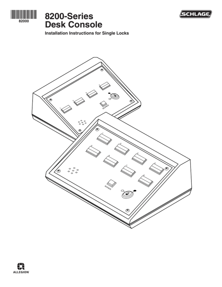
*82000* 8200-Series 82000 Desk Console 2 3 4 Installation Instructions for Single Locks E NC LE 1 SI 1 2 5 3 6 4 7 8 SI LE NC E LIST OF PARTS • • • • Pushbuttons/Hole Plugs Maintained or Momentary Pushbutton Assembly* Hole Plug* Keyswitch Keys (2) Pushbuttons/Hole Plugs 2 1 4 3 1 2 3 4 5 6 7 8 SILENCE SILENCE Maintained or Momentary Pushbutton Assemby* Keyswitch Keys (2) Hole Plug* * Each console will have installed any combination of these in the switch/hole plug position SPECIFICATIONS/FUNCTION Power • 24 VDC ± 15% • 50 milliamp internal console excluding lamps • For UL applications, the power source shall be a UL294 listed class 2 (power limited) power supply Pushbutton (Momentary or Maintained) • 1 Amp, 24 VDC Lamps (Green or Red) • 0.04 Amps @ 24 VDC (#85 lamp) Terminal Blocks • Maximum of 14 Ga wire, 18-22 recommended • Rated torque/screw size 0.50 Nm/M³ Alarm Output • 0.5 Amp @ 24 VDC common to all zones, protected by automatically resetable breaker Keyswitch • Off (CCW) – Powers NC (FS) outputs and removes power from NO (FSE) outputs by breaking pushbutton common. Powering NC contacts can be field modified to eliminate this feature - see User Selectable Options • ON (CW) – Powers pushbutton common and allows the pushbuttons to have full control over the zone Reset Button • Momentary pushbutton that resets the internal latching horn and the Alarm Output that has been triggered by voltage on the RED terminal Temperature Range • 32°F – 120°F 2 Wiring Examples DESK CONSOLE TYPICAL EXTERNAL HORN WIRING TYPICAL CHEXIT WIRING GRN RED BLK C WHT NO GRN NC ORN TB(1-8) 24VDC POWER SUPPLY CHEXIT YEL FIRE ALARM GND GRA VIO BRN BLU +24 RED CX GND SC 3 DPS FA CM+ CMNO C +24 TB 9 681 24 VDC POWER SUPPLY PWR INPUT GND ALARM OUTPUT +24 TYPICAL WIRING FOR EXTERNAL ALARM OUTPUT HORN (LIGHT, SOUNDER ETC.) MAX. LOAD 1/2A @24VDC • When pushbutton is depressed, the CHEXIT device is disarmed and the GREEN light is on. • When pushbutton is released, the CHEXIT is armed and the pushbutton light is off. • If the pushbar is depressed while the CHEXIT is armed, the RED light will come on and the alarm will sound. Typical L1910 Wiring • When pushbutton is depressed, the L1910 horn is disarmed (passage through door allowed) and GREEN light in pushbutton will come on. • When pushbutton is released, the L1910 horn is armed (passage through door will sound alarm) and RED light in pushbutton will come on. • When pushbutton is depressed, the magnetic lock is unlocked and the GREEN light will come on. • When the pushbutton is released, the magnetic lock is locked and the pushbutton light is off. • If the door is forced open while the magnetic lock is locked, the RED light will come on and the alarm will sound. L1910. DPS DOOR POS. SWITCH BLU RED YEL DESK CONSOLE SHOWN WITH DOOR CLOSED GRN RED C NO BLK NC TB(1-3) RED GRN VIO L1910 HORN BLU 0 24VDC POWER SUPPLY TB 9 GND +24 Typical Magnetic Lock with DPS & HFS Option Wiring DESK CONSOLE MAGNETIC LOCK NO C GRN NC RED NC C NO NC TB(1-8) C NC DOOR POSITION SWITCH HOLD FORCE SENSOR V+ MAGNETIC V- LOCK 0 24VDC POWER SUPPLY GND +24 TB 9 3 Typical 6000 Series Electric Strike Wiring ELECT STRIKE W/DS OPTION (FSE) YEL LATCHBOLT DEADBOLT SWITCH RED BLU DESK CONSOLE VIO GRN WHT RED GRA • When pushbutton is depressed, the electric strike is unlocked and the GREEN light is on. • When pushbutton is released, the strike is locked and the pushbutton light is off. • If the door is forced open while the strike is locked, the RED light will come on and the alarm will sound. • When pushbutton is depressed, the EL devices are unlocked and the GREEN light in the pushbutton will come on. • When pushbutton is released, the EL devices are locked and the pushbutton light is off. • Refer to PS914 x 900-2RS PCB instructions for proper wiring instructions for the EL device. SOLENOID SWITCH C NO LOCK SOLENOID NC TB(1-8) 0 NOTE: IN4001 OR IN4004 DIODE ACROSS SOLENOID. DOOR SHOWN CLOSED AND LOCKED 24VDC POWER SUPPLY TB 9 GND +24 Typical EL Device Wiring DESK CONSOLE EL DEVICE GRN RED C NO EL DEVICE NC TB(1-8) 0 24VDC POWER SUPPLY GND +24 TB 9 INSTALLATION/WIRING 1REMOVE ALL FOUR (4) SCREWS I/O Panel 4 2REMOVE I/O PANEL AND DRILL HOLE FOR WIRE USED If required, use a strain relief or cable connector for wires. Cable Connector I/O Panel To Internal Wiring Conduit Size Drill Size Z\x” M\,” C\v” 1Z\,” 3REASSEMBLE BOX 4REMOVE ALL FOUR (4) FACEPLATE SCREWS Faceplate 1 2 5 3 6 4 7 8 SIL EN CE 5 5CONNECT PROPER GAUGE WIRE TO THE APPROPRIATE TERMINALS AS REQUIRED • TB1 corresponds to pushbutton 1, TB2 to pushbutton 2, etc. • Keep excess wire out of console for easier installation. • For ease of wiring, faceplate with pushbuttons can be unplugged and reconnected later. NC GRN NO RED C RED NO GRN NC NC GRN NO RED C RED GRN NC NC GRN NO RED ZONE 6 ZONE 5 C RED NO GRN NC NC GRN NO RED C C ZONE 4 ZONE 3 NO C C ZONE 2 ZONE 1 ZONE 7 ZONE 8 C RED NO GRN NC 0 + + 6RECONNECT PUSHBUTTONS, IF NEEDED Make sure they are properly polarized, then replace faceplate and secure screws. Pushbuttons Faceplate 1 Pushbutton 2 5 3 6 4 7 8 Header Plug SIL EN CE Post P. C. Board 6 TROUBLESHOOTING Pushbutton contacts and lights do not work • Check that the pushbutton connector is fully seated in the proper plug Lamp does not work • Check for 24 VDC on the RED or GRN terminal • Replace the bulb - see Maintenance MAINTENANCE Lamp Replacing Replace with #85 lamp as shown below Lens Cap (Pull Straight Out, Snap Fit) Pulling Lamp Extractor Will Remove Lamp Push New Lamp Into Place Pushbutton Pushbutton Holder Spring Replacing/Adding a Pushbutton Pushbuttons can be replaced, changed (either from maintained to momentary, or vice versa) or added. With the faceplate removed, using a small flathead screwdriver, remove the two pushbutton holder springs. Remove the pushbutton assembly from the faceplate. Pushbutton Pushbutton Holder Spring Note: Make sure pushbuttons are plugged into the proper zones per Table 1 and the red lens is in the lower position. Cleaning Use a mild cleaner to clean the console off. Do not spray directly onto the face. 7 USER SELECTABLE OPTIONS 1. Pushbutton common isolation: Normally all pushbutton commons are connected to +PWR INPUT when keyswitch is ON. To isolate any pushbutton from +PWR INPUT voltage, cut proper diode (CR20-27) see Table 1. 2. NC contact control: When the keyswitch is in the OFF position, the NC output is powered (pushbutton has no control). To control NC contacts, select and cut proper diode (CR9-16), see Table 1. 3. Red terminal latch disable: Application of 24 VDC to the RED terminal not only lights the RED light, but latches the internal buzzer and 24 VDC on the Alarm Output. If the latching feature is not desired on a zone, cut proper diode (CR1-8), see Table 1. PUSHBUTTON G GRN R RED C TYPICAL ONE ZONE BUTTON 3 CR(1-8) NO (FAIL SECURE) NC (FAIL SAFE) 2 1 CR(20-27) CR(9-16) (OFF) + KEYSWITCH (ON) + PWR INPUT _ _ LATCH CIRCUIT ALARM OUTPUT 0 Table 1 Pushbutton (or TB#) 1 2 3 4 5 6 7 8 P1 P2 P3 P4 P5 P6 P7 P8 Pushbutton Common Isolation CR20 CR21 CR22 CR23 CR24 CR25 CR26 CR27 NC Contact Control CR9 CR10 CR11 CR12 CR13 CR14 CR15 CR16 Red Term. Latch Disable CR1 CR2 CR3 CR4 CR5 CR6 CR7 CR8 PCB Plug Customer Service 1-877-671-7011 www.allegion.com/us © Allegion 2014 Printed in U.S.A. 82000 Rev. 12/14-e


