A 27 MHZ TEMPERATURE COMPENSATED MEMS OSCILLATOR
advertisement
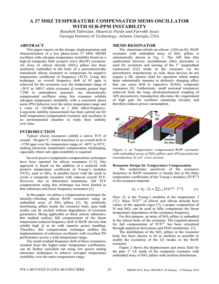
A 27 MHZ TEMPERATURE COMPENSATED MEMS OSCILLATOR WITH SUB-PPM INSTABILITY Roozbeh Tabrizian, Mauricio Pardo and Farrokh Ayazi Georgia Institute of Technology, Atlanta, Georgia, USA ABSTRACT MEMS RESONATOR This paper reports on the design, implementation and characterization of a low phase-noise 27 MHz MEMS oscillator with sub-ppm temperature instability based on a high-Q composite bulk acoustic wave (BAW) resonator. An array of silicon dioxide (SiO2) pillars has been uniformly embedded in the body of a piezoelectrically transduced silicon resonator to compensate its negative temperature coefficient of frequency (TCF). Using this technique, an overall frequency drift of 83 ppm is achieved for the resonator over the temperature range of 20°C to 100°C while resonator Q remains greater than 7,500 in atmospheric pressure. An electronically compensated oscillator using this resonator exhibits sub-ppm temperature instability with a consistent phase noise (PN) behavior over the entire temperature range and a value of -101dBc/Hz at 1 kHz offset-frequency. Long-term stability measurement has been carried out for both temperature-compensated resonator and oscillator in an environmental chamber to study their stability over time. The aluminum-nitride-on-silicon (AlN-on-Si) BAW resonator with embedded array of SiO2 pillars is schematically shown in Fig. 1. The AlN thin film sandwiched between molybdenum (Mo) electrodes is used for excitation and sensing of the 1st longitudinal extensional (LE) mode in the resonator via the piezoelectric transduction; as such, these devices do not require a DC electric field for operation which makes them substantially immune to dielectric charging effect that can cause drift in capacitive Si/SiO2 composite resonators [6]. Furthermore, small motional resistances achieved from the large electromechanical coupling of AlN piezoelectric transduction alleviates the requirement of high gain for oscillator sustaining circuitry and therefore reduces power consumption. INTRODUCTION Typical silicon resonators exhibit a native TCF of around 30 ppm/°C, which translates to an overall drift of ~3750 ppm over the temperature range of 40°C to 85°C, making electronic temperature compensation challenging, especially where sub–ppm instability is required. Figure 1: a) Temperature compensated BAW resonator with embedded array of SiO2 pillars and AlN piezoelectric transduction; b) AA’ cross section. Several passive temperature compensation techniques have been reported for silicon resonators [1-5]. One approach is based on the addition of a material with positive temperature coefficient of Young’s modulus (TCE), such as SiO2, in parallel layers with the stack to create a composite resonator with reduced overall TCF. However, due to fabrication limitations, full TCF compensation using this technique has been limited to thin substrates and lower frequency resonators [1]. Resonator Design for Temperature Compensation The temperature sensitivity of the resonance frequency in BAW resonators is mainly due to the finite temperature coefficients of the Young’s modulus (TCE(n)) of the resonator material: = In this paper, we utilize a compensation technique for laterally-vibrating silicon BAW resonators using an embedded array of SiO2 pillars [1]. By uniformly distributing pillars inside the resonator body, pure bulk modes can be excited without degradation of resonator parameters. Being applicable to thick silicon substrates, this method realizes full compensation of the linear temperature-induced frequency drift of BAW devices that exhibit high Q in air with superior power handling. Therefore, this compensation technique enables the implementation of reference oscillators with excellent PN performance across a wide temperature range. The small residual frequency drift of these resonators, resulted from the higher-order temperature coefficients, can be further cancelled out using low power analog electronic techniques to achieve sub-ppm temperature instability over the entire temperature range. 978-1-4673-0325-5/12/$31.00 ©2012 IEEE 1+ ( ) (1) Here, ET is the Young’s modulus at the temperature T (°C). Since TCE(1) of silicon and silicon dioxide have values of the opposite signs [7], a proper composition of Si and SiO2 can be used to fully compensate the linear temperature dependence of the resonance frequency. For this purpose, an array of SiO2 pillars is embedded in the silicon body of the resonator. The required amount for full compensation of TCE(1) has been calculated through analytical derivations and FEM simulations [1]. The distribution of the SiO2 pillars in the resonator body has been chosen to be as uniform as possible to enable the excitation of the LE modes in the BAW resonator. Figure 2 shows the displacement and stress field for the pure 1st LE mode of the composite resonator with embedded array of SiO2 pillars with uniform distribution. 23 MEMS 2012, Paris, FRANCE, 29 January - 2 February 2012 Fabrication Process To fabricate the composite resonators, trenches with slightly tapered sidewalls are first etched into a silicon wafer for desired depth (i.e. 20um). This is followed by the conformal deposition of LPCVD TEOS at 850 °C, partially filling trenches and covering the top surface of the wafer. The substrate is then annealed at 1050°C for two hours to densify TEOS and improve surface roughness. Since a nearly smooth surface is required for the deposition of Mo electrodes and high-quality AlN, the top SiO2 layer thinned down by wet etching in HF to improve surface smoothness. The rest of the fabrication process is similar to the one reported in [5] with some minor modifications. Figure 4 shows an SEM picture of a fabricated temperature-stable 27MHz resonator with uniformly distributed embedded array of SiO2 pillars. Figure 2: Simulated 1st LE (a) mode shape and (b) stress field of AlN-on-Si BAW resonator with embedded array of SiO2 pillars. For the 1st LE mode, the resonance frequency can be calculated from: (2) where W is the width (frequency defining dimension) of the resonator and Eeq and eq are the equivalent Young’s modulus and density of the composite structure. Considering (2), the full compensation of the TCE(1) of silicon using silicon dioxide results in a quadratic temperature-frequency characteristic for the compensated resonator due to higher order TCE(n) (n>1). Since in the temperature range of interest (-40°C to 85°C) the effect of TCE(2) in the frequency drift is much smaller compared to TCE(1) [7], the composite resonator shows ~45 reduction in the overall frequency drift in this range. Furthermore, the resulting parabolic temperaturefrequency characteristic provides a local-zero-TCF | < ) where the resonance operation region (| frequency is insensitive to temperature variations (i.e. lim ( ) = 0). Figure 2 compares temperature dependence of the equivalent Young’s modulus of the composite resonator with silicon and silicon dioxide. Figure 4: (a) SEM image of AlN-on-Si BAW resonator with embedded array of SiO2 pillars; (b) close-up view of SiO2 pillars in the body of the resonator. Resonator Characterization Figure 5 shows the frequency response of the temperature compensated composite resonator. Figure 3: Qualitative comparison of the temperature dependency of Young’s modulus for Si, SiO2 and their composition (not to scale the quantities); equations for Si and SiO2 extracted from [2] and [7]. Figure 5: Frequency response of the temperature compensated resonator in Fig. 4; inset shows the spurious free response in a large frequency span. 24 A Q of 7,600 has been achieved in air with the insertion loss of ~15 dB. The device shows a spuriousfree frequency response within a 10MHz span around the resonance frequency. Figure 6 shows the temperature characteristic of the device. maximize the available tuning range, electronic cancellation of these shunt capacitances is achieved by using active inductors to resonate out the shunt parasitic capacitances. For this purpose, high-Q tunable active inductors are implemented on-chip to provide the specific value of the emulated inductor required for parasitic compensation. Selectable on-chip capacitor-banks in addition to a phase-shifter have been placed in the feedback loop to provide required electronic tuning of the resonance frequency at the operating temperature. Figure 8 shows the system block diagram for the compensated MEMS oscillator. Figure 6: Temperature characteristic of the resonance frequency and Q of the resonator in Fig. 4; local-TCF is approximately zero at 40°C. A frequency drift of 83 ppm has been achieved over the temperature range of 20°C to 100°C with parabolic temperature-frequency characteristic. The composite temperature-stable resonator has a consistent Q higher than 7,500 over the entire temperature range. A long term frequency measurement has been performed on these devices at an elevated temperature of 100°C in vacuum to investigate the instability of their resonance frequency over time. A small frequency variation of 2.4 ppm over a period of 50 days of operation (Fig. 7) has been observed, which is attributed to the low accuracy of the temperature control unit of the vacuum probe station ( 1°C) and finite local TCF of the device at 100°C (~3ppm/°C). Figure 8: The system block diagram for the 27 MHz temperature-compensated MEMS oscillator. A TIA-based sustaining amplifier is used to reduce the input referred noise [8], and to minimize the loading of the resonant device. The inverter-based TIA offers about 100dB gain and embeds the phase-shifter for tuning. The switched scheme of the capacitor banks provides about 60ppm of tuning (in discrete steps of 15ppm/step) while the TIA phase-shifter provides 60ppm of continuous tuning with high precision. Oscillator Characterization Figure 9 shows the PN performance measured for 6 temperature points. Figure 7: Steady-state stability measurement for passively temperature-compensated resonator. TUNABLE MEMS OSCILLATOR Oscillator Design Electronic tuning can be used to further reduce the thermal drift of the MEMS oscillator. The main challenge in using circuit techniques for this task is the presence of large parasitic shunt capacitances in the device, resulted from large dielectric constant of AlN and extended Mo pads required for efficient transduction. These shunt capacitances considerably limit the frequency pulling range and hence the electronic tuning efficiency. To Figure 9: Phase noise performance of temperature compensated oscillator at 6 temperature points showing consistent behavior over the temperature range. 25 A PN of -101dBc/Hz at 1 kHz offset-frequency with consistent behavior across the entire temperature range is measured for the temperature-compensated MEMS oscillator. This is the lowest reported PN to date for any temperature compensated MEMS oscillator with sub-ppm temperature instability. Figure 10 shows the result of stability measurement for the oscillator operating in air, which has been carried out in a chamber with temperature-control accuracy of 0.3°C at 6 different temperature points after applying required tuning to operate at a constant frequency with an accuracy of 0.1 Hz (< 4ppb). This accuracy is provided by fine frequency tuning available from phase shifter and is limited by the resolution of frequency measurement setup (Agilent 53181A). Interestingly, the stability result at 40°C, which corresponds to the local-zero-TCF region of the resonator, shows a variation of less than 100ppb. temperature instability level over the entire temperature range of -20°C to 80°C. Furthermore, the stability result at 40°C, which corresponds to the local-zero-TCF region of the resonator, shows a variation of less than 100 ppb. A PN of -101dBc/Hz at 1 kHz offset-frequency with consistent behavior across the entire temperature range is measured for the oscillator which is the lowest reported phase noise to date for any temperature compensated MEMS oscillator with sub-ppm temperature instability. ACKNOWLEDGEMENTS This work has been supported by the Integrated Device Technology (IDT), Inc. The authors would like to thank the OEM Group for AlN thin film deposition. REFERENCES [1] R. Tabrizian, G. Casinovi and F. Ayazi, "Temperature-Stable High-Q AlN-on-Silicon Resonators with Embedded Array of Oxide Pillars," Solid-State Sensors, Actuators, and Microsystems Workshop (Hilton Head 2010), June 2010, pp. 100101. [2] R. Melamud, et al, "Temperature Insensitive Composite Micromechanical Resonators," Journal of Microelectromechanical Systems, Vol. 18, No. 6, pp. 1409-1419, 2009. [3] A.K. Samarao, G. Casinovi, and F. Ayazi, “Passive TCF Compensation in High Q Silicon Micromechanical Resonators,” IEEE International Conference on Micro Electro Mechanical Systems (MEMS 2010), Hong Kong, Jan. 2010, pp. 116-119. [4] A.K. Samarao and F. Ayazi, “Temperature Compensation of Silicon Micromechanical Resonators via Degenerate Doping,” IEEE International Electron Devices Meeting (IEDM 2009), Baltimore, MD, Dec. 2009, pp. 789-792. [5] W. Pan and F. Ayazi, “Thin-Film Piezoelectric-onSubstrate Resonators with Q Enhancement and TCF Reduction,” IEEE International Conference on Micro Electro Mechanical Systems (MEMS 2010), Hong Kong, Jan. 2010, pp. 104-107. [6] G. Bahl et al, “Observation of fixed and mobile charge in composite MEMS resonators”, Solid-State Sensors, Actuators, and Microsystems Workshop, Hilton Head 2008, Hilton Head, SC, USA, pp 102105. [7] H. J. McSkimin, “Measurement of elastic constants at low temperatures by means of ultrasonic waves— Data for silicon and germanium single crystals, and for fused silica,” J. Appl. Phys., vol. 24, no. 8, pp. 988–997, Aug. 1953. [8] H.M. Lavasani, W. Pan, F. Ayazi, "An electronically temperature-compensated 427MHz low phase-noise AlN-on-Si micromechanical reference oscillator," 2010 IEEE Radio Frequency Integrated Circuits Symposium (RFIC), pp.329-332, 2010. Figure 10: Steady-state stability measurement for fullycompensated oscillator after applying active tuning to operate at f0 0.1 Hz (a) at 6 temperature points; (b) at 40°C. CONCLUSION A uniformly distributed array of SiO2 pillars have been embedded in the silicon body of an AlN-on-Si resonator to fully compensate the linear term of temperature dependency of the resonance frequency without degradation of resonator parameters. A quadratic temperature characteristic resulted from smaller higher order temperature coefficients of Young’s modulus shows an overall drift of 83 ppm over the temperature range of -20°C to 100°C which is ~45 smaller compared to uncompensated silicon resonators. An oscillator implemented using these temperature-compensated composite resonators employs active tuning mechanisms to cancel out the residual frequency drift of the MEMS device to an accuracy of <4ppb, while showing sub-ppm CONTACT *R. Tabrizian, tel: +1-404-259-7322; roozbeh@gatech.com 26
