Summer 2008
Issue 3, Volume 2
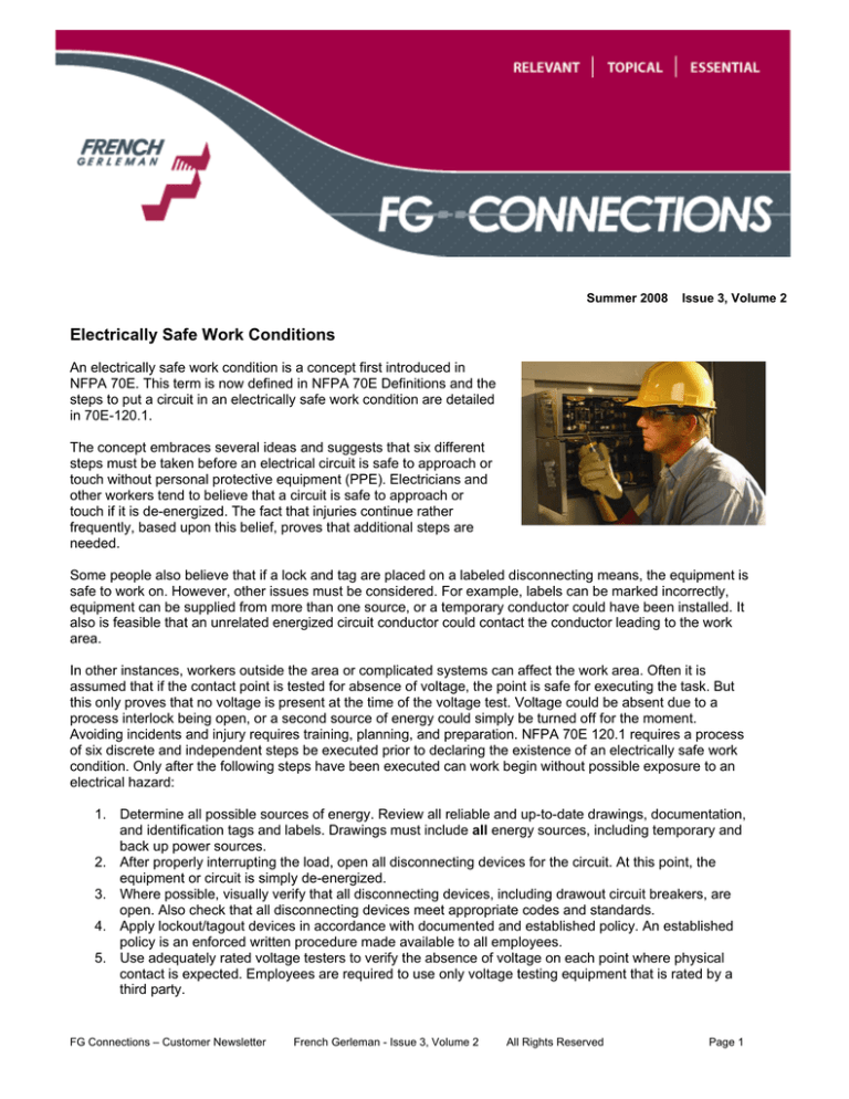
Electrically Safe Work Conditions
An electrically safe work condition is a concept first introduced in
NFPA 70E. This term is now defined in NFPA 70E Definitions and the
steps to put a circuit in an electrically safe work condition are detailed
in 70E-120.1.
The concept embraces several ideas and suggests that six different
steps must be taken before an electrical circuit is safe to approach or
touch without personal protective equipment (PPE). Electricians and
other workers tend to believe that a circuit is safe to approach or
touch if it is de-energized. The fact that injuries continue rather
frequently, based upon this belief, proves that additional steps are
needed.
Some people also believe that if a lock and tag are placed on a labeled disconnecting means, the equipment is
safe to work on. However, other issues must be considered. For example, labels can be marked incorrectly,
equipment can be supplied from more than one source, or a temporary conductor could have been installed. It
also is feasible that an unrelated energized circuit conductor could contact the conductor leading to the work
area.
In other instances, workers outside the area or complicated systems can affect the work area. Often it is
assumed that if the contact point is tested for absence of voltage, the point is safe for executing the task. But
this only proves that no voltage is present at the time of the voltage test. Voltage could be absent due to a
process interlock being open, or a second source of energy could simply be turned off for the moment.
Avoiding incidents and injury requires training, planning, and preparation. NFPA 70E 120.1 requires a process
of six discrete and independent steps be executed prior to declaring the existence of an electrically safe work
condition. Only after the following steps have been executed can work begin without possible exposure to an
electrical hazard:
1. Determine all possible sources of energy. Review all reliable and up-to-date drawings, documentation,
and identification tags and labels. Drawings must include all energy sources, including temporary and
back up power sources.
2. After properly interrupting the load, open all disconnecting devices for the circuit. At this point, the
equipment or circuit is simply de-energized.
3. Where possible, visually verify that all disconnecting devices, including drawout circuit breakers, are
open. Also check that all disconnecting devices meet appropriate codes and standards.
4. Apply lockout/tagout devices in accordance with documented and established policy. An established
policy is an enforced written procedure made available to all employees.
5. Use adequately rated voltage testers to verify the absence of voltage on each point where physical
contact is expected. Employees are required to use only voltage testing equipment that is rated by a
third party.
FG Connections – Customer Newsletter
French Gerleman - Issue 3, Volume 2
All Rights Reserved
Page 1
6. Where the possibility of induced voltage or stored energy exists, ground the phase conductors before
touching them. Where it is reasonable to expect that the conductors could be re-energized due to
accidental contact with another source of energy, install grounding devices rated for the available fault
current.
Until these six steps have been adequately executed, some potential of exposure to an electrical hazard still
exists.
Note: While putting circuits/equipment in an electrically safe work condition, safe work practices appropriate
for the circuit voltage and arc-flash energy level should be used, including adequate personal protective
equipment [70E-120.2(A)]. When a disconnect is opened, the circuit may be de-energized but the circuit is not
yet considered to be in an electrically safe work condition until all the above steps of 70E-120.1 are
successfully completed. For instance, voltage testing of each conductor, which is a necessary step while
putting a circuit in an electrically safe work condition, requires adequate PPE. Essentially the same
requirement is in OSHA 1910.333(b) which considers de-energized circuits as energized until all the
appropriate steps have been completed successfully.
The Role of Overcurrent Protective Devices in Electrical Safety:
If an arcing fault occurs while a worker is in close proximity, the survivability of the worker is mostly dependent
upon (1) the characteristics of the overcurrent protective devices, (2) the arc-fault current, and (3) precautions
the worker has taken prior to the event, such as wearing PPE appropriate for the hazard. The selection and
performance of overcurrent protective devices play a significant role in electrical safety. Extensive tests and
analysis by industry have shown that the energy released during an arcing fault is related to two
characteristics of the overcurrent protective device protecting the affected circuit:
1. The time it takes the overcurrent protective device to open. The faster the fault is cleared by the
overcurrent protective device, the lower the energy released.
2. The amount of fault current the overcurrent protective device lets through. Current-limiting overcurrent
protective devices may reduce the current let-through (when the fault current is within the currentlimiting range of the overcurrent protective device) and can reduce the energy released.
Lowering the energy released is better for both worker safety and equipment protection.
Article provided by:
© Cooper Bussmann, Inc. Reprinted with permission from the Cooper Bussmann® Safety BASICs™ Handbook.
The statements, recommendations, and claims made in this newsletter represent the opinions of the contributing manufacturers and
French Gerleman. They should not be construed as a claim of warranty or performance of equipment. Neither French Gerleman nor
anyone related to or involved with French Gerleman will be held liable for any claims or damages arising out of the publication of this
newsletter, whether made in tort, contract, intellectual property or otherwise.
Reference Section 12, French Gerleman General Terms and Condition of Sale. For a complete copy of the French Gerleman General
Terms and Condition of Sale, visit www.frenchgerleman.com.
FG Connections – Customer Newsletter
French Gerleman - Issue 3, Volume 2
All Rights Reserved
Page 2


