General Purpose
Power Relay
FEATURES
• Small package design
• DPDT has a fine silver
contact with 5 A capability
• 4PDT has a gold-plated
silver contact with 3 A
capability
• High dielectric strength
(1,800 Vac)
• High reliability and long life
• Ultra-high sensitivity with
quick response time
(20 ms max.)
• Options include LED
indicator, diode protection,
and LED indicator/diode
protection
• UL listed, CE certified,
CSA certified
TYPICAL APPLICATIONS
• Control panels
• Elevator panels
• Machine tools
• Test equipment
WARNING
PERSONAL INJURY
DO NOT USE these
products as safety or
emergency stop devices or
in any other application
where failure of the product
could result in personal
injury.
Failure to comply with
these instructions could
result in death or serious
injury.
Sensing and Control
SZR-MY Series
®
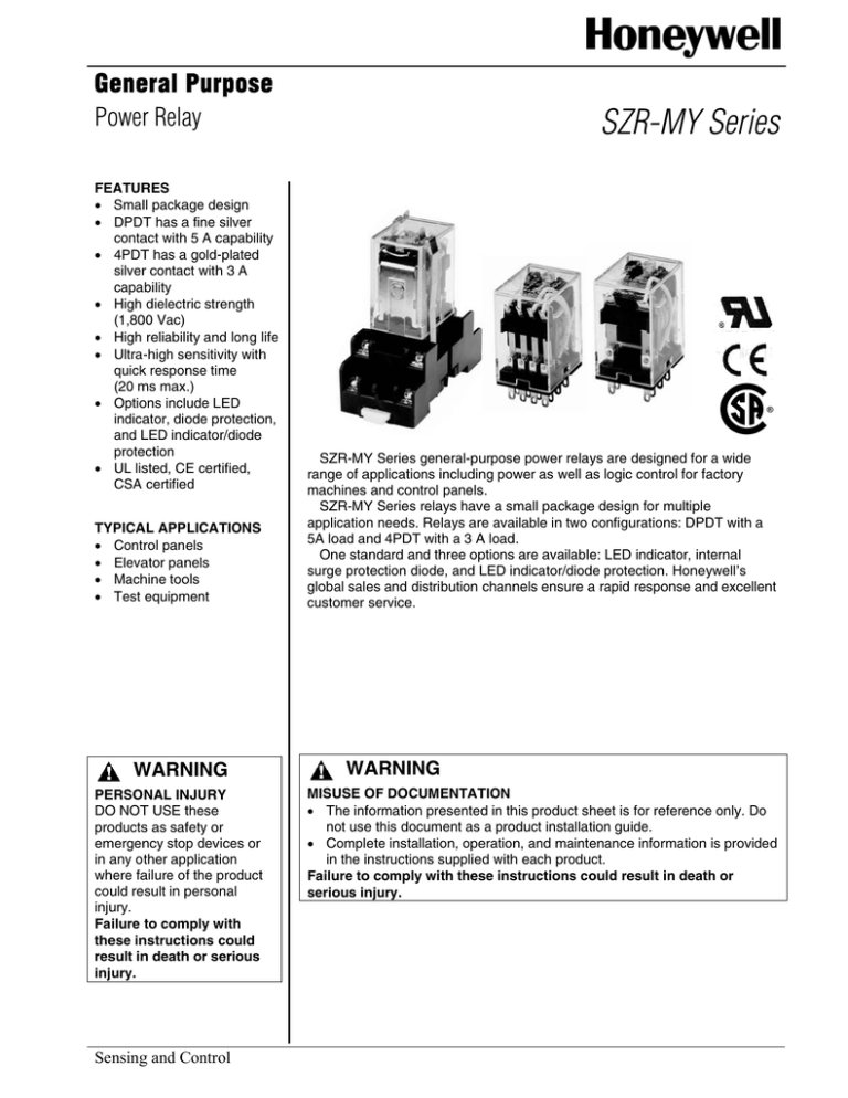
SZR-MY Series general-purpose power relays are designed for a wide
range of applications including power as well as logic control for factory
machines and control panels.
SZR-MY Series relays have a small package design for multiple
application needs. Relays are available in two configurations: DPDT with a
5A load and 4PDT with a 3 A load.
One standard and three options are available: LED indicator, internal
surge protection diode, and LED indicator/diode protection. Honeywell’s
global sales and distribution channels ensure a rapid response and excellent
customer service.
WARNING
MISUSE OF DOCUMENTATION
• The information presented in this product sheet is for reference only. Do
not use this document as a product installation guide.
• Complete installation, operation, and maintenance information is provided
in the instructions supplied with each product.
Failure to comply with these instructions could result in death or
serious injury.
General Purpose
Power Relays
SZR-MY Series
RELAY MODEL SELECTION GUIDE
Type
Terminal
Standard
Plug-in/Solder
PCB
LED Indicator
Plug-in/Solder
DIODE surge suppression
LED indicator + surge suppression
Contact
Catalog Listing
DPDT
SZR-MY2-1
4PDT
SZR-MY4-1
DPDT
SZR-MY2-1P
4PDT
SZR-MY4-1P
DPDT
SZR-MY2-N1
4PDT
SZR-MY4-N1
DPDT
SZR-MY2-D1
4PDT
SZR-MY4-D1
DPDT
SZR-MY2-X1
4PDT
SZR-MY4-X1
SOCKETS – REQUIRED ACCESSORIES
Din-rail Mounting
Solder Terminal
PCB Terminal
Relay Contact
DPDT
For use with
SZR-MY2-1, -N1, D1, -X1
SZX-SMF-08N
SZX-SMB-08
SZX-SMB-08P
4PDT
For use with
SZR-MY4-1, -N1, D1, -X1
SZX-SMF-14N
2 Honeywell • Sensing and Control
SZX-SMB-14
SZX-SMB-14P
General Purpose
Power Relays
SZR-MY Series
CONTACT RATINGS
Type
Load
Ratings
DPDT
Resistive Load (p.f. = 1)
Inductive load
(p.f. = 0.4, L/R = 7 ms)
Rated load
220 Vac, 5A
24 Vdc, 5A
Carry current
Max. operating
voltage
Max. operating
current
Max. switching
capacity
Min. permissible
load
4PDT
Resistive Load (p.f. = 1)
Inductive load
(p.f. = 0.4, L/R = 7 ms)
220 Vac, 2A
24 Vdc, 2A
220 Vac, 3A
24 Vdc, 3A
220 Vac, 0.8 A
24 Vdc, 1.5 A
5A
250 Vac, 125 Vdc
3A
250 Vac, 125 Vdc
5A
3A
1,100 VA, 120 W
440 VA, 48 W
660 VA, 72 W
1 mA, 5 Vdc
176 VA, 16 W
1 mA, 1 Vdc
COIL RATINGS
Rated
Voltage
(V)
AC
Coil Inductance (H)
Coil
resistance
Armature
OFF
Armature
ON
0.04
0.08
(Ω)
6
214.1
183
12.2
Pick-up
Voltage
(V)
Dropout
Voltage
(V)
Maximum
Voltage
(V)
Power
Consumption
(W)
Approx.
12
106.5
91
46
0.17
0.33
24
53.8
46
180
0.69
1.3
Max.
Min.
50
25.7
22
788
3.22
5.66
75 %
30%
100/110
11.7/12.9
10/11
3,750
14.54
24.6
Approx
1.0 W to 1.2 W
(60 Hz)
110%
110/120
9.9/10.8
8.4/9.2
4,430
19.2
32.1
0.9 W to 1.1 W
200/220
6.2/6.8
5.3/5.8
12,950
54.75
94.07
(60 Hz)
220/240
4.8/5.3
4.2/4.6
18,790
83.5
136.4
40
0.17
0.33
6
DC
Rated Current
(mA)
50 Hz
60 Hz
150
12
75
160
0.73
1.37
Max.
Min.
24
36.9
650
3.2
5.72
75%
10%
48
18.5
2,600
10.6
21.0
100/110
9.1/10
11,000
45.6
86.2
Approx.
110%
0.9 W
Note 1: The rated current and coil resistance are measured at a coil temperature of 23 °C [73.4 °F] with tolerances of +15%,
-20% for AC rated current and ± 15% for DC coil resistance.
Note 2: The rated current of N1 and X1 types is 4 mA higher than the value in the table above.
Honeywell • Sensing and Control
3
General Purpose
Power Relays
SZR-MY Series
SPECIFICATIONS
Contact material
Contact resistance
Operate time
Release time
Operating
Mechanical
frequency
Electrical
Silver
Max. 50 MOhm
Max. 20 ms
Max. 20 ms
18,000 operations per hour
1,800 operations per hour
Insulation resistance
Dielectric withstand voltage
Min. 100 Mw at 500 Vdc
1,800 Vac 50 Hz/60 Hz for one minute between non-continuous current
carrying terminals and between coil thermals and contact terminals
Vibration
Mechanical durability
10 Hz to 55 Hz at double amplitude of 1.0 mm
resistance
Malfunction durability
10 Hz to 55 Hz at double amplitude of 1.0 mm
Shock resistance Mechanical durability
1,000 m/s2 (approx. 100 g)
Malfunction durability
200 m/s2 (approx. 20 g)
Service life
Mechanical
AC: Min. 50 million operations (at operating frequency of 18,000 operations/hour)
DC: Min. 100 million operations (at operating frequency of 18,000 operations/hour)
Electrical
DPDT: Min. 500,000 operations (at operating frequency of 1,800 operations/hour)
4PDT: Min. 200,000 operations (at operating frequency of 1,800 operations/hour)
Weight
Approximately 35 g
Note 1: The data shown above are of initial value
CHARACTERISTIC DATA
AC inductive
p.f.=0.4
DC resistive
1
0.5
DC inductive
L/R=7ms
0.1
5 10
)
4
1,000
500
AC110V
AC220V
100
50
DC24V
10
0
50 100
500
Rated operating voltage(V)
3
4
5
6
AC resistive
5
3
AC inductive
p.f.=0.4
DC resistive
1
0.5
DC inductive
L/R=7ms
0.1
5 10
50 100
500
Rated operating voltage(V)
4 Honeywell • Sensing and Control
500
AC110V p.f.=0.4
AC220V p.f.=0.4
100
50
DC24V L/R=7ms
10
7 8
Current(A)
0
1
2
Current(A)
)
Induc tive Load
4
)
4
10
1,000
Resistive Load
Number of operations(× 10
4PDT
Rated operating current(A)
Max. Switching capacity
1 2
Number of operations(× 10
5
Induc tive Load
1,000
500
AC110V
AC220V
100
50
DC30V
10
0
1
2
Number of operations(× 10
AC resistive
10
4
)
Resistive Load
Number of operations(× 10
DPDT
Rated operating current(A)
Max. Switching capacity
1,000
500
AC110V p.f.=0.4
DC30V L/R=7ms
100
50
AC220V p.f.=0.4
10
0
3
Current(A)
0.5
1
1.5
Current(A)
General Purpose
Power Relays
SZR-MY Series
HOLDING CLIPS
• Holding clips are included with the sockets
• Holding clips for the SMF-08N and SMF-14N cannot be removed once inserted
• Holding clips for all SMB sockets are wire for easy removal
• Holding clips are to be inserted into the slots provided on the socket
DIMENSIONS (For reference only – mm/in)
Figure 1. Dimensions
For SZX-SMF-08N and SZX-SMF-14N sockets
Figure 2. Dimensions
For all SZX-SMB sockets
5,0
[0.20]
14,5
[0.57]
29,0 [1.14]
22,0 [0.87]
6,5
[0.26]
4,6 [0.18]
6,2
[0.24]
39,6 [1.56]
49,9 [1.96]
2,2
[0.09
]
Honeywell • Sensing and Control
15°
5
General Purpose
Power Relays
SZR-MY Series
CATALOG LISTING MATRIX
SZR – MY 2 - ___
1
P - AC110-120V
Terminal Type
__ = Solder/Plug-in
P = PCB
Mounting Type
1 = Terminal
Poles
2 = DPDT
4 = 4PDT
Amp Rating:
MY = 5 A or 3 A
LY = 10 A
Product Type
General Purpose Relay
6 Honeywell • Sensing and Control
Option Type
__ = No Indicator or Diode
D = Internal Surge Protection Diode
N = Red LED Operation Indicator
X = LED and Diode
Voltage Rating:
AC6V
=
AC12V
=
AC24V
=
AC50V
=
AC100V
=
AC110-120V =
AC200V
=
AC220V
=
AC220-240V =
DC6V
=
DC12V
=
DC24V
=
DC48V
=
DC100V
=
6 Vac
12 Vac
24 Vac
50 Vac
100 Vac
110/120 Vac
200 Vac
220 Vac
220/240 Vac
6 Vdc
12 Vdc
24 Vdc
48 Vdc
100 Vdc
General Purpose
Power Relays
SZR-MY Series
Max. 28,0 [1.10]
6,3
[0.25]
0,5
[0.02]
2,6
[0.10]
FIGURE 3. DIMENSION, CIRCUIT DIAGRAM, TERMINAL ARRANGEMENT, AND MOUNTING HOLE FOR
SZR-MY2-1, SZR-MY2-N1, SZR-MY2-D1, and SZR-MY2-X1
8 - O 1,2 [0.05] x 3 Holes
0,5
[0.02]
Max. 21,5
[0.85]
Max. 36,0 [1.42]
MY2-1
6,0
[0.24]
MY2-N1 AC
MY2-N1 DC
MY2-D1
MY2-X1
1
4
1
4
1
4
1
4
1
4
5
8
5
8
5
8
5
8
5
8
9
12
9
12
9
13
14
13
14
13
-
+
12
9
14
13
-
+
12
9
14
13
12
-
+
14
Bottom view
3,5
[0.14]
0,5
[0.02]
Max. 36,0 [1.42]
Max. 21,5
[0.85]
6,0
[0.24]
The circuit diagram is the same wit standard type of SZR-MY2-1 or the SZR-MY4-1
Honeywell • Sensing and Control
7
3,3
[0.13]
1,0
[0.04]
Max. 28,0
[1.10]
6,3
[0.25]
0,5
[0.02]
FIGURE 4. DIMENSION, CIRCUIT DIAGRAM, TERMINAL ARRANGEMENT, AND MOUNTING HOLE FOR
SZR-MY2-1P and SZR-MY4-1P
General Purpose
Power Relays
SZR-MY Series
Max. 28,0
[1.10]
6,3
[0.25]
2,6
[0.10]
0,5
[0.02]
FIGURE 5. DIMENSION, CIRCUIT DIAGRAM, TERMINAL ARRANGEMENT, AND MOUNTING HOLE FOR
SZR-MY4-1, SZR-MY4-N1, SZR-MY4-D1, and SZR-MY4-X1
14 - O 1.2 [0.05] x 3 Holes
Max. 21,5
[0.85]
0,5
[0.02]
Max. 36,0 [1.42]
MY4-1
6,0
[0.24]
MY4-N1 AC
MY4-N1 DC
MY4-D1
MY4-X1
1
2
3
4
1
2
3
4
1
2
3
4
1
2
3
4
1
2
3
4
5
6
7
8
5
6
7
8
5
6
7
8
5
6
7
8
5
6
7
8
9
10
11
12
9
10
11
12
9
10
11
12
9
10
11
12
9
10
11
13
14
13
14
13
-
+
14
13
-
+
14
13
-
+
Bottom view
FIGURE 6. CIRCUIT DRAWING FOR SZR-MY2- and SZR-MY4-
4PDT
DPDT
13.2
14- 1.3
0.1
13.2
3.75
8 Honeywell • Sensing and Control
8- 1.3
0.1
6.35
6.3
12.65
4.3
4.1
4.4
12
14
General Purpose
Power Relays
SZR-MY Series
SOCKETS
FIGURE 7. SZX-SMF-08N
18,0
[0.70]
30,0 [1.18]
25,0 [0.99]
35,2 [1.39]
62,0 ± 0,1 [2.44 ± .004]
26,0
[1.02]
15,6
[0.61]
3,0
[0.12]
2 - O 4,5 [0.18] Holes
26,0 [1.02]
45,0 [1.77]
4,2
[0.17]
62,0 ± 0,1
[2.44 ± .004]
35,2
[1.39]
2-M3 or 2-M4
15,6
[0.61]
3,0
[0.12]
3,9
[0.15]
26,0
[1.02]
45,0
[1.77]
4,2
[0.17]
62,0 [2.44]
6,0
[0.24]
3,9
[0.15]
62,0 [2.44]
6,0
[0.24]
FIGURE 8. SZX-SMF-14N
2-M3 or 2-M4
2 - O 4,5 [0.18] Holes
18,0
[0.70]
26,0 [1.02]
30,0 [1.18]
Max. 61,0 [2.40]
Max. 61,0 [2.40]
25,0 [0.99]
FIGURE 9. SZX-SMB-08
FIGURE 10. SZX-SMB-14
14 - 3 x O 1,2 [0.05] Holes
8 - 3 X O 1,2 [0.05] Holes
2,7
[0.11]
7,7
[0.30]
Max. 25,5
[1.00]
2,7
[0.11]
2,6 [0.10]
7,7
[0.30]
Max. 29,5
[1.16]
0,3
[0.01]
Max. 29,5 [1.16]
Max. 25,5 [1.00]
0,3
[0.01]
Max 24,0 [0.94]
Max. 24,0 [0.94]
2,6
[0.10]
Max. 20,0
[0.79]
21,4 ± 0,2
0.84 ± .008
Honeywell • Sensing and Control
25,8 ± 0,2
[1.02 ± .008]
38,5 [1.52]
25,8 ± 0,2
[1.02 ± .008]
Max. 38,5 [1.52]
Max. 20,0
[0.79]
21,4 ± 0,2
[0.84 ± .008]
9
General Purpose
Power Relays
SZR-MY Series
2,7
[0.11]
4,2
[0.17]
WARRANTY/REMEDY
Honeywell warrants goods of its manufacture as
being free of defective materials and faulty
workmanship. Contact your local sales office for
warranty information. If warranted goods are
returned to Honeywell during the period of
coverage, Honeywell will repair or replace without
charge those items it finds defective. The
foregoing is Buyer’s sole remedy and is in lieu
of all other warranties, expressed or implied,
including those of merchantability and fitness
for a particular purpose.
Specifications may change without notice. The
information we supply is believed to be accurate
and reliable as of this printing. However, we
assume no responsibility for its use.
Sensing and Control
www.honeywell.com/sensing
Honeywell
11 West Spring Street
Freeport, Illinois 61032
009550-4-EN IL50 GLO 0104 Printed in USA
Copyright 2003-2004 Honeywell International Inc. All Rights Reserved.
4,1
[0.16]
4,4
[0.17]
38,5 [1.52]
12,65
[0.50]
8 - O 2,0 [0.08] Holes
13,2
[0.52]
6,4
[0.25]
6,4
[0.25]
6,35
[0.25]
5,8
[0.23]
4,1
[0.16]
Max. 16,5
[0.65]
13,2
[0.52]
Max. 29,5
[1.16]
2,6
[0.10]
4,2
[0.17]
12,65
[0.50]
Max. 16,5
[0.65]
6,35
[0.25]
2,6
[0.10]
38,5 [1.52]
Max. 22,0
[0.87]
0,3
[0.01]
Max. 29,5 [1.16]
Max. 25,5 [1.00]
0,3 [0.01]
2,7
[0.11]
4,3
[0.17]
Max. 22,0 [0.87]
5,8
[0.23]
4,3
[0.17]
FIGURE 12. SZX-SMB-14P
Max. 25,5
[1.00]
FIGURE 11. SZX-SMB-08P
14 - O 2,0 [0.08] Holes
While we provide application assistance
personally, through our literature and the
Honeywell web site, it is up to the customer to
determine the suitability of the product in the
application.
For application assistance, current specifications,
or name of the nearest Authorized Distributor,
contact a nearby sales office. Or call:
1-800-537-6945 USA/Canada
1-815-235-6847 International
FAX
1-815-235-6545 USA
INTERNET
www.honeywell.com/sensing
info.sc@honeywell.com


