- Tommy Gate
advertisement

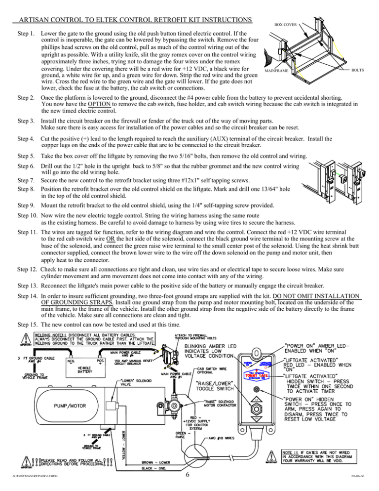
ARTISAN CONTROL TO ELTEK CONTROL RETROFIT KIT INSTRUCTIONS BOX COVER Step 1. Lower the gate to the ground using the old push button timed electric control. If the control is inoperable, the gate can be lowered by bypassing the switch. Remove the four phillips head screws on the old control, pull as much of the control wiring out of the upright as possible. With a utility knife, slit the gray romex cover on the control wiring approximately three inches, trying not to damage the four wires under the romex covering. Under the covering there will be a red wire for +12 VDC, a black wire for ground, a white wire for up, and a green wire for down. Strip the red wire and the green wire. Cross the red wire to the green wire and the gate will lower. If the gate does not lower, check the fuse at the battery, the cab switch or connections. MAINFRAME BOLTS Step 2. Once the platform is lowered to the ground, disconnect the #4 power cable from the battery to prevent accidental shorting. You now have the OPTION to remove the cab switch, fuse holder, and cab switch wiring because the cab switch is integrated in the new timed electric control. Step 3. Install the circuit breaker on the firewall or fender of the truck out of the way of moving parts. Make sure there is easy access for installation of the power cables and so the circuit breaker can be reset. Step 4. Cut the positive (+) lead to the length required to reach the auxiliary (AUX) terminal of the circuit breaker. Install the copper lugs on the ends of the power cable that are to be connected to the circuit breaker. Step 5. Take the box cover off the liftgate by removing the two 5/16" bolts, then remove the old control and wiring. Step 6. Drill out the 1/2" hole in the upright back to 5/8" so that the rubber grommet and the new control wiring will go into the old wiring hole. Step 7. Secure the new control to the retrofit bracket using three #12x1" self tapping screws. Step 8. Position the retrofit bracket over the old control shield on the liftgate. Mark and drill one 13/64" hole in the top of the old control shield. Step 9. Mount the retrofit bracket to the old control shield, using the 1/4" self-tapping screw provided. Step 10. Now wire the new electric toggle control. String the wiring harness using the same route as the existing harness. Be careful to avoid damage to harness by using wire tires to secure the harness. Step 11. The wires are tagged for function, refer to the wiring diagram and wire the control. Connect the red +12 VDC wire terminal to the red cab switch wire OR the hot side of the solenoid, connect the black ground wire terminal to the mounting screw at the base of the solenoid, and connect the green raise wire terminal to the small center post of the solenoid. Using the heat shrink butt connector supplied, connect the brown lower wire to the wire off the down solenoid on the pump and motor unit, then apply heat to the connector. Step 12. Check to make sure all connections are tight and clean, use wire ties and or electrical tape to secure loose wires. Make sure cylinder movement and arm movement does not come into contact with any of the wiring. Step 13. Reconnect the liftgate's main power cable to the positive side of the battery or manually engage the circuit breaker. Step 14. In order to insure sufficient grounding, two three-foot ground straps are supplied with the kit. DO NOT OMIT INSTALLATION OF GROUNDING STRAPS. Install one ground strap from the pump and motor mounting bolt, located on the underside of the main frame, to the frame of the vehicle. Install the other ground strap from the negative side of the battery directly to the frame of the vehicle. Make sure all connections are clean and tight. Step 15. The new control can now be tested and used at this time. UP DN G:\DISTMAN\REPAIR\6.DWG 6 05-06-06


