Infrared Point Detector for Combustible Gas Detection
advertisement

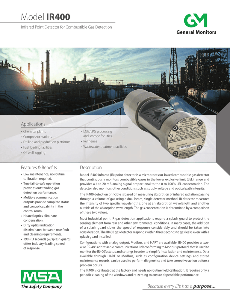
Model IR400 Infrared Point Detector for Combustible Gas Detection Applications • • • • • Chemical plants Compressor stations Drilling and production platforms Fuel loading facilities Oil well logging • LNG/LPG processing and storage facilities • Refineries • Wastewater treatment facilities Features & Benefits Description • Low maintenance; no routine calibration required. • True fail-to-safe operation provides outstanding gas detection performance. • Multiple communication outputs provide complete status and control capability in the control room. • Heated optics eliminate condensation. • Dirty optics indication discriminates between true fault and cleaning requirements. • T90 < 3 seconds (w/splash guard) offers industry-leading speed of response. Model IR400 infrared (IR) point detector is a microprocessor-based combustible gas detector that continuously monitors combustible gases in the lower explosive limit (LEL) range and provides a 4 to 20 mA analog signal proportional to the 0 to 100% LEL concentration. The detector also monitors other conditions such as supply voltage and optical path integrity. The IR400 detection principle is based on measuring absorption of infrared radiation passing through a volume of gas using a dual beam, single detector method. IR detector measures the intensity of two specific wavelengths, one at an absorption wavelength and another outside of the absorption wavelength. The gas concentration is determined by a comparison of these two values. Most industrial point IR gas detection applications require a splash guard to protect the sensing element from rain and other environmental conditions. In many cases, the addition of a splash guard slows the speed of response considerably and should be taken into consideration. The IR400 gas detector responds within three seconds to gas leaks even with a splash guard installed. Configurations with analog output, Modbus, and HART are available. IR400 provides a twowire RS-485 addressable communications link conforming to Modbus protocol that is used to monitor the IR400’s status and settings in order to simplify installation and maintenance. Data available through HART or Modbus, such as configuration device settings and stored maintenance records, can be used to perform diagnostics and take corrective action before a problem occurs. The IR400 is calibrated at the factory and needs no routine field calibration. It requires only a periodic cleaning of the windows and re-zeroing to ensure dependable performance. Because every life has a purpose... System Specifications DeteCtOR tyPe MeASURInG RAnGe GASeS DeteCtOR lIfe ACCURACy @ 25°C zeRO DRIft ReSPOnSe tIMe WITH SPLASH gUARD ReADOUt/RelAy DISPlAy MODUleS ACCeSSORIeS ClASSIfICAtIOn Infrared absorption type 0 to 100% LEL 0 to 100% by volume (methane only) Methane, propane, ethane, ethylene, butane, hexane, pentane, benzene Consult factory for other gases greater than 5 years ± 3% LEL at ≤ 50% LEL reading ± 5% LEL at > 50% LEL reading < 2% per year T50 ≤ 1.5 s, T60 ≤ 1.5 s, T90 ≤ 3 s Except ethylene where T60 ≤ 2 s and T90 ≤ 4 s electrical Specifications InPUt POweR AnAlOG SIGnAl START UP, FAULT (non-HART) START UP, FAULT (HART)* CAL, ZERO, gAS CHECk* DIRTy OPTICS* 0 TO 100% LEL OVER-RANgE eMC CAble ReqUIReMentS DC110; TA102A; IR4000 display, and relay alarms Junction box, duct mount junction box, calibration cup, flow block, splash guard, rain guard, portable purge calibrator Class I, Zone 1, IIB + H2 (Ta=-40° C to +75° C) Ex d, IIB + H2 T5 gb Ex tb IIIC, T100° C Db, IP66 (Ta=-60° C to +75° C) Two years APPROvAlS ATEx, IECEx, MED, DNV gL, CE, FM 6310, 6320 and CSA 22.2 No. 152 EN 60079-29-1 Performance Approved HART Registered, SIL 3 suitable FM Certified to IEC 61508 0-21.7 mA (600 ohms max.) 0 mA 1.25 mA 1.5 mA 2.0 mA 4 to 20 mA (proportional) 20 to 21.7 mA Complies with EN 50270, EN 61000-6-4 Max. distance between IR400 and power source @ 24 VDC nominal (20 ohm loop resistance): 14 AWg (2.0 mm2) - 3600 ft (1100 m) Max. distance for analog output (500 ohms max): 14 AWg (2.0 mm2) - 9000 ft. (2740 m) fAUltS MOnItOReD Re-calibration error, EPROM checksum error, optics failure/blockage; low supply voltage, EEPROM checksum error, reference or active lamp failure, heater failure, time to re-zero unit, short circuit on CAL_IO wire RS-485 OUtPUt Modbus RTU, suitable for linking up to 128 units or up to 247 units with repeaters bAUD RAte wARRAnty 20-36 VDC @ 200 mA max. 24 VDC nominal 2400, 4800, 9600, or 19200 BPS HARt (OPtIOnAl) HART 6, HART Device Descriptor available. AMS aware wIReleSS COMMUnICAtIOn Available with ELPRO Technologies wireless devices Mechanical Specifications environmental Specifications DIAMeteR OPeRAtInG teMPeRAtURe RAnGe FM, CSA, gOST-R ATEx, IECEx ETHyLENE StORAGe teMPeRAtURe RAnGe OPeRAtInG HUMIDIty RAnGe lenGtH -40° F to +167° F (-40° C to +75° C) -76° F to +167° F (-60° C to +75° C) -40° F to +140° F (-40° C to +60° C) -58° F to +185° F (-50° C to +85° C) 10% to 95% RH, non-condensing weIGHt ALUMINUM STAINLESS STEEL MOUntInG InGReSS PROteCtIOn HOUSInG * Under HART, the analog output minimum level can be configured as 3.5 mA or as stated above, depending on user selection. StAnDARD COnfIGURAtIOn 2.9” (74 mm) 8.87” (225 mm) 3 lbs (1.35 kg) 6 Ibs (2.7 kg) ¾" NPT Type 4x, IP66 Aluminum 6061-T6 alloy or 316 stainless steel IR400-0-01-1-2-0-1-0 Methane, 4-20 mA, Modbus, aluminum, splashguard w/screen, no junction box Specifications subject to change without notice. Note: This Bulletin contains only a general description of the products shown. While uses and performance capabilities are described, under no circumstances shall the products be used by untrained or unqualified individuals and not until the product instructions including any warnings or cautions provided have been thoroughly read and understood. Only they contain the complete and detailed information concerning proper use and care of these products. Specifications subject to change without notice. ID 1465-05-MC / Dec 2015 Corporate Headquarters: MSA 1000 Cranberry Woods Drive Cranberry Township, PA 16066 United States +1-724-776-8600 info.us@MSAsafety.com Design Center: General Monitors 26776 Simpatica Circle Lake Forest, CA 92630 United States +1-949-581-4464 info.gm@MSAsafety.com © MSA 2015 Printed in U.S.A. Additional locations can be found on our web site: www.MSAsafety.com MSAsafety.com/detection


