F
O
Y
T
Old School Horn Kit Y
R
E
T
P
c
R
O
n
E
i
P
,
t
O
n
i
i
R
d
,
P
i
t
i
d
d
i
d
i
INSTALLATION INSTRUCTIONS
for ididit Old School Straight Steering Columns
PART NUMBER’S: 1012360010 & 1012360025
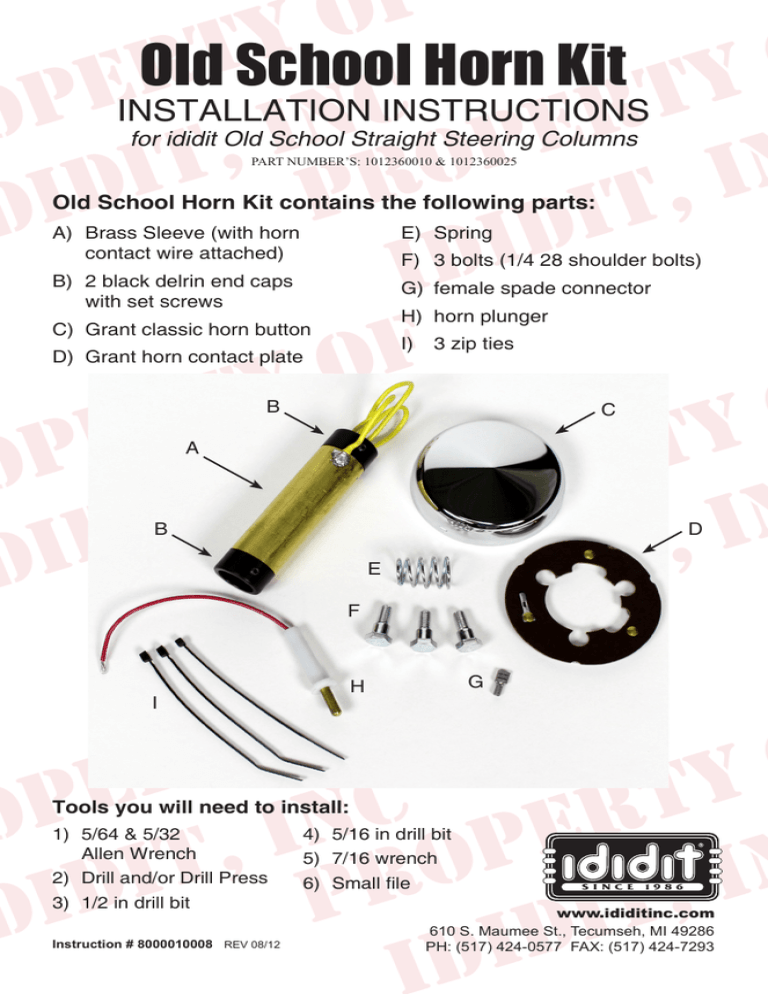
Old School Horn Kit contains the following parts:
A) Brass Sleeve (with horn
contact wire attached)
E)Spring
B) 2 black delrin end caps
with set screws
G) female spade connector
F) 3 bolts (1/4 28 shoulder bolts)
F
O
Y
T
R
Y
E
T
P
c
R
O
n
E
i
P
,
t
O
n
i
i
R
d
,
P
i
t
i
d
d
i
d
i
F
O
Y
T
R
Y
E
T
P
c
R
O
n
E
i
P
,
t
O
n
i
i
R
d
,
P
i
t
i
d
d
di
H) horn plunger
C) Grant classic horn button
I) 3 zip ties
D) Grant horn contact plate
B
C
A
B
D
E
F
G
H
I
Tools you will need to install:
1) 5/64 & 5/32
Allen Wrench
4) 5/16 in drill bit
2) Drill and/or Drill Press
6) Small file
3) 1/2 in drill bit
Instruction # 8000010008 REV 08/12
5) 7/16 wrench
S I N C E
1 9 8 6
www.ididitinc.com
610 S. Maumee St., Tecumseh, MI 49286
PH: (517) 424-0577 FAX: (517) 424-7293
1. After shortening your Old School steering column to the desired
length (see Old School Straight column instructions) position the assembled
column underneath the dash. From here you will determine the
location of the keyhole that will need to be drilled in order to insert
the horn plunger into the column tube. The hole can be placed
behind the underdash mount, at the floor board, underneath the
carpet, the choice is yours.
Diagram 1
Measurement 1
Top of
Measure from the top of the
column to determine where the
horn plunger will be located. Mark
this position on the column tube.
This mark will be the center point
for the smaller hole in the keyhole
(see Diagram 1).
Column
2. Remove the column from under the dash once you have marked
your preferred horn plunger location.
Diagram 2
1/2 in (Center to Center)
Top of
Measurement 2
Column
3.To complete the keyhole,
measure
1/2”
from
measurement 1 (towards top
of column). Mark this position.
This measurement will be the
center point for the larger hole
(see Diagram 2).
Measurement 1
4. Disassemble the column in order to separate the tube and shaft.
Once both holes are drilled, file
and deburr all rough edges in
order to prevent wear or chaffing
of horn wire.
5/16” Drill
5. Use a 1/2” drill bit to drill the
Diagram 3
larger hole. Center the drill on
1/2” Drill
measurement 2. Use a 5/16”
Top of
drill bit to drill the smaller hole.
Column
Measurement 1 will be your
Measurement 2
center mark. (see Diagram
3). We strongly recommend
using a drill press when drilling the
keyhole.
Measurement 1
Finished horn plunger keyhole
6. Next, slide the brass sleeve with the black delrin end caps onto the
column shaft. (Make sure the upper bearing is positioned above the
sleeve on the shaft). Position the brass sleeve so the horn plunger
keyhole will be centered above it.
Figure 1: Set
screws should
contact the flat
side of shaft.
Figure 2: Set
screws should
be offset from
horn wire.
Flat of
column shaft
Figure 4
Figure 3
7. Position the set screws on the delrin end caps so that the screws
contact the flat side of the shaft (see Figure 1). Also check to make
sure the screws are offset from the soldered horn wire to ensure
easy tightening (see Figure 2).
8. Pass the horn wire through the bearing between the inside diameter
of the bearing and the flat of the shaft (see Figure 3). Then pass
the wiring through the head of the column using the existing hole
(see Figure 4).
9. Straighten the horn wire on the shaft using the supplied wire ties.
a)Space the wire ties evenly along the shaft.
b)Position the ties so that the wire tie head is on the flat of the
column shaft to prevent scraping noises, etc.
c)Trim off excess wire tie.
F
O
Y
T
R
Y
E
T
P
c
RO it, in OPER i
R
d
,
P
i
t
i
id
d
i
d
i
F
O
Y
T
R
Y
E
T
P
c
RO it, in OPER i
R
d
,
P
i
t
i
id
d
i
d
i
F
O
Y
T
R
Y
E
T
P
c
RO it, in OPER i
R
d
,
P
i
t
i
id
d
i
10.Once you have all the horn kit components in position on the shaft
you can begin to reassemble the column. Slide the column tube
over the shaft and install lower bearing, wavy washer & locking
collar per column instructions.
11.Install the horn plunger into the tube by pushing the spring loaded
plunger into the larger hole, slide it into position by pulling it down
into the narrow end of the keyhole. The pressure of the spring,
along with gravity will hold the horn plunger in place.
12.Connect the horn plunger wire to the negative side of the horn relay
or simply follow the directions in your wiring kit.
Need Further Assistance?
ididit has been serving the rodding community since 1986 and we take pride
in our outstanding customer service. If you need further assistance, feel free
to call us at (517) 424-0577 during our normal business hours. You can also
email us at tech@ididit.com. Go to www.ididitinc.com/contact-us for hours
of operation.
Need A Visual?
Go to www.ididitinc.com/videos to watch installation videos, tech tips &
more!
No part of this guide may be reprinted, reproduced or utilized in
any form without the express written permission of ididit
2012 ididit
All Rights Reserved
Printed in the USA
ididit
610 S. Maumee St., Tecumseh, MI 49286
(517) 424-0577 • (517) 424-7293 fax
www.ididitinc.com


