ULTRA-BROADBAND ISOLATION BALUN BAL
advertisement

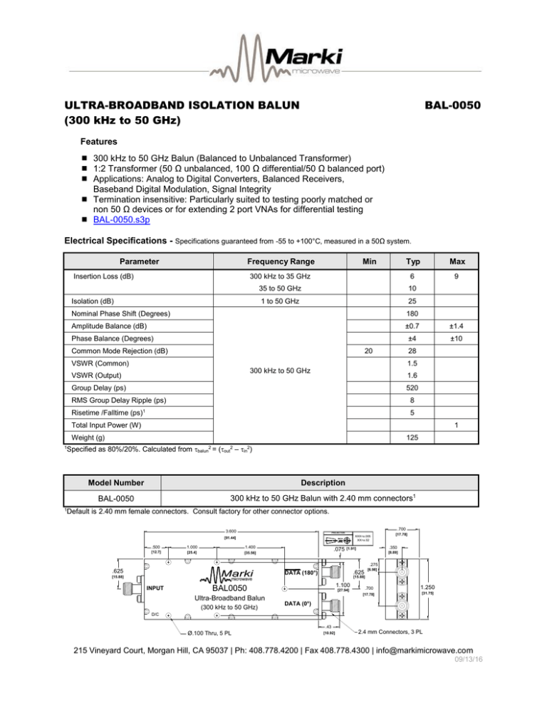
ULTRA-BROADBAND ISOLATION BALUN (300 kHz to 50 GHz) BAL-0050 Features 300 kHz to 50 GHz Balun (Balanced to Unbalanced Transformer) 1:2 Transformer (50 Ω unbalanced, 100 Ω differential/50 Ω balanced port) Applications: Analog to Digital Converters, Balanced Receivers, Baseband Digital Modulation, Signal Integrity Termination insensitive: Particularly suited to testing poorly matched or non 50 Ω devices or for extending 2 port VNAs for differential testing BAL-0050.s3p Electrical Specifications - Specifications guaranteed from -55 to +100°C, measured in a 50Ω system. Parameter Frequency Range Insertion Loss (dB) Typ Max 300 kHz to 35 GHz 6 9 35 to 50 GHz 10 1 to 50 GHz 25 Isolation (dB) Min Nominal Phase Shift (Degrees) 180 Amplitude Balance (dB) ±0.7 ±1.4 ±4 ±10 Phase Balance (Degrees) Common Mode Rejection (dB) 20 28 VSWR (Common) 1.5 300 kHz to 50 GHz VSWR (Output) 1.6 Group Delay (ps) 520 RMS Group Delay Ripple (ps) Risetime /Falltime (ps) 8 1 5 Total Input Power (W) 1 Weight (g) 125 Specified as 80%/20%. Calculated from balun2 = (out2 – in2) 1 Model Number Description BAL-0050 300 kHz to 50 GHz Balun with 2.40 mm connectors1 1 Default is 2.40 mm female connectors. Consult factory for other connector options. .700 3.600 PROJECTION [91.44] XXX=±.005 XX=±.02 INCH [MM] .500 1.000 1.400 [12.7] [25.4] [35.56] .075 [17.78] .350 [1.91] [8.89] .275 .625 .625 DATA (180°) [15.88] INPUT 1.100 BAL0050 Ultra-Broadband Balun (300 kHz to 50 GHz) [6.98] [15.88] [27.94] .700 1.250 [17.78] [31.75] DATA (0°) D/C .43 Ø.100 Thru, 5 PL [10.92] 2.4 mm Connectors, 3 PL 215 Vineyard Court, Morgan Hill, CA 95037 | Ph: 408.778.4200 | Fax 408.778.4300 | info@markimicrowave.com 09/13/16 ULTRA-BROADBAND ISOLATION BALUN (300 kHz to 50 GHz) BAL-0050 Page 2 Block Diagram 180° 180° 0° 0° Single ended to differential Differential to single ended Typical Performance 0 0 Common -9 -12 -15 -18 Output 2 -10 -15 -20 Output 1 -21 Output 2 -25 -24 0 5 10 15 20 25 30 35 40 45 50 0 55 5 10 15 20 25 30 35 40 45 50 55 Frequency (GHz) Frequency (GHz) Fig. 2. Return loss for common port and output ports. Fig. 1. Common to output port insertion loss. 5 200 4 195 3 Phase Balance (degree) Amplitude Balance (dB) Output 1 -5 -6 Return Loss (dB) Insertion Loss (dB) -3 2 1 0 -1 -2 -3 190 185 180 175 170 165 -4 160 -5 0 5 10 15 20 25 30 35 40 45 50 55 Frequency (GHz) Fig. 3. Amplitude balance between output ports. 0 5 10 15 20 25 30 35 40 45 50 55 Frequency (GHz) Fig. 4. Phase balance between output ports. 215 Vineyard Court, Morgan Hill, CA 95037 | Ph: 408.778.4200 | Fax 408.778.4300 | info@markimicrowave.com 09/13/16 ULTRA-BROADBAND ISOLATION BALUN (300 kHz to 50 GHz) BAL-0050 0 0 -5 -5 -10 -10 -15 Isolation (dB) Common Mode Rejection (dB) Page 3 -20 -25 -30 -15 -20 -25 -35 -30 -40 -35 -45 -40 0 5 10 15 20 25 30 35 40 45 50 55 0 5 10 15 Frequency (GHz) 25 30 35 40 45 50 55 50 55 Frequency (GHz) Fig. 5. Common mode rejection. Fig. 6. Output to output port isolation. 660 120 620 90 Differential Group Delay (ps) Group Delay (ps) 20 580 540 500 460 420 380 60 30 0 -30 -60 -90 -120 0 5 10 15 20 25 30 35 40 45 50 55 0 Frequency (GHz) 10 15 20 25 30 35 40 45 Frequency (GHz) Fig. 7. Group delay. INPUT EYE 5 Fig. 8. Differential group delay. DATA INVERTED DATA 50 Gb/s Fig. 9. Oscilloscope measurements of the BAL-0050 with a 50 Gb/s PRBS pattern in single ended-todifferential mode. Eye diagrams are taken with a 231-1 PRBS input demonstrating minimal eye distortion/closure afforded by the extremely low frequency operation of the balun (<300 kHz). 215 Vineyard Court, Morgan Hill, CA 95037 | Ph: 408.778.4200 | Fax 408.778.4300 | info@markimicrowave.com 09/13/16 ULTRA-BROADBAND ISOLATION BALUN (300 kHz to 50 GHz) BAL-0050 Page 4 OUTPUT SINGLE ENDED NEGATIVE INPUT POSITIVE INPUT 40 Gb/s POSITIVE OUTPUT INPUT SINGLE ENDED NEGATIVE OUTPUT Fig. 10. Oscilloscope measurements of the BAL-0050 with a 40 Gb/s PRBS pattern. Bit pattern is measured with a 27-1 PRBS input demonstrating extremely good pulse fidelity for both differential-to-single ended and single ended to differential mode conversions. DC Interface Port Description Common (Unbalanced Port) The common port is DC connected to the 0o port through a resistor and to ground through a resistor. 0o Port (Balanced) The 0o port is DC connected to the common port through a resistor and to ground through a resistor. 180o Port (Balanced) The 180o port is DC shorted to ground. DC Interface Schematic Marki Microwave reserves the right to make changes to the product(s) or information contained herein without notice. Marki Microwave makes no warranty, representation or guarantee regarding the suitability of its products for any particular purpose, nor does Marki Microwave assume any liability whatsoever arising out of the use of or application of any product. 215 Vineyard Court, Morgan Hill, CA 95037 | Ph: 408.778.4200 | Fax 408.778.4300 | info@markimicrowave.com 09/13/16


