force on a current in a magnetic field
advertisement
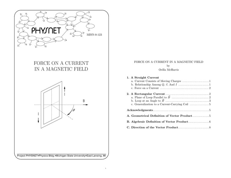
MISN-0-123 FORCE ON A CURRENT IN A MAGNETIC FIELD by Orilla McHarris FORCE ON A CURRENT IN A MAGNETIC FIELD 1. A Straight Current a. Current Consists of Moving Charges . . . . . . . . . . . . . . . . . . . . . 1 b. Relationship Among Q, ~v , And I . . . . . . . . . . . . . . . . . . . . . . . . 1 c. Force on a Current . . . . . . . . . . . . . . . . . . . . . . . . . . . . . . . . . . . . . . 2 2. A Rectangular Current . . . . . . . . . . . . . . . . . . . . . . . . . . . . . . . . . . 2 ~ ............................. 2 a. Plane of Loop Parallel to B ~ b. Loop at an Angle to B . . . . . . . . . . . . . . . . . . . . . . . . . . . . . . . . . . 3 c. Generalization to a Current-Carrying Coil . . . . . . . . . . . . . . . 5 I B Acknowledgments. . . . . . . . . . . . . . . . . . . . . . . . . . . . . . . . . . . . . . . . . . . .5 I A. Geometrical Definition of Vector Product . . . . . . . . . . . . . 5 B. Algebraic Definition of Vector Product . . . . . . . . . . . . . . . . 6 C. Direction of the Vector Product . . . . . . . . . . . . . . . . . . . . . . . . 8 Project PHYSNET · Physics Bldg. · Michigan State University · East Lansing, MI 1 ID Sheet: MISN-0-123 THIS IS A DEVELOPMENTAL-STAGE PUBLICATION OF PROJECT PHYSNET Title: Force on a Current in a Magnetic Field Author: Orilla McHarris, Lansing Community College Version: 3/27/2000 Evaluation: Stage 0 Length: 1 hr; 24 pages Input Skills: 1. Vocabulary: current (MISN-0-117); magnetic field, magnetic force (MISN-0-122). 2. Calculate the torque on a rod with respect to a parallel axis, given a constant force perpendicular to the rod (MISN-0-5). 3. Visualize the rotational motion produced by a given torque (MISN-0-33). 4. Calculate the magnetic force on a moving charged particle (MISN0-122). Output Skills (Knowledge): The goal of our project is to assist a network of educators and scientists in transferring physics from one person to another. We support manuscript processing and distribution, along with communication and information systems. We also work with employers to identify basic scientific skills as well as physics topics that are needed in science and technology. A number of our publications are aimed at assisting users in acquiring such skills. Our publications are designed: (i) to be updated quickly in response to field tests and new scientific developments; (ii) to be used in both classroom and professional settings; (iii) to show the prerequisite dependencies existing among the various chunks of physics knowledge and skill, as a guide both to mental organization and to use of the materials; and (iv) to be adapted quickly to specific user needs ranging from single-skill instruction to complete custom textbooks. New authors, reviewers and field testers are welcome. K1. Derive the expression Q~v = I ~` relating a set of charges and their common velocity to their equivalent value as a current. K2. Starting from the Lorentz force, derive the expression for the force on a length current-carrying wire in a uniform magnetic field. Output Skills (Problem Solving): S1. Calculate the force on a straight section of a current-carrying wire in a given uniform magnetic field. S2. Calculate the mechanical torque on a rectangular current loop in a given uniform magnetic field. S3. Calculate the torque on an n-turn rectangular coil in a given uniform magnetic field. Post-Options: 1. “The Magnetic Field of a Moving Charge: Magnetic Interactions” (MISN-0-124). 2. “The Magnetic Field of a Current: The Ampere-Laplace Equation” (MISN-0-125). PROJECT STAFF Andrew Schnepp Eugene Kales Peter Signell Webmaster Graphics Project Director ADVISORY COMMITTEE D. Alan Bromley E. Leonard Jossem A. A. Strassenburg Yale University The Ohio State University S. U. N. Y., Stony Brook Views expressed in a module are those of the module author(s) and are not necessarily those of other project participants. c 2001, Peter Signell for Project PHYSNET, Physics-Astronomy Bldg., ° Mich. State Univ., E. Lansing, MI 48824; (517) 355-3784. For our liberal use policies see: http://www.physnet.org/home/modules/license.html. 3 4 MISN-0-123 1 FORCE ON A CURRENT IN A MAGNETIC FIELD MISN-0-123 2 passing the point: I= by Orilla McHarris (Q/`)d` Qv dQ = = . dt d`/v ` Remember, however, that the velocity of positive charges and the current are in the same direction, so actually: ~ = Q~v . I` 1. A Straight Current 1a. Current Consists of Moving Charges. An electric current consists of moving charges. Thus, if a current is placed in a magnetic field, it will be subject to a magnetic force just as single moving charges are. The magnetic force on one charge q moving with velocity ~v in a ~ is:1 magnetic field B ~ (1) F~B = q~v × B. The magnetic force on a current is just the sum of such forces on the current’s component charges. Assuming these charges all travel with the same velocity: F~Total = ~ + q2~v × B ~ + . . . + qn~v × B ~ q1~v × B ~ (q1 + q2 + . . . + qn )~v × B, = ~ Q~v × B, = 1b. Relationship Among Q, ~v , And I. In order to state the magnetic force in terms of the measured current, I, we must find the relationship of Q and ~v to I. The amount of charge dQ in a small length of conducting wire d` is given by the overall charge per length, Q/` times the length d`: Q (2) dQ = d` ` If we hold a current measuring instrument at one point and watch a length d` of charge go by, for all of d` (and therefore, all of dQ) to pass the point takes a time dt = d`/v (3) where v is the speed of the charges making up the current. Now the definition of current at a point is the amount of charge per unit time “Force on a Charged Particle in a Magnetic Field” (MISN-0-122). (5) For convenience, we will transfer the designation of the current’s direction to the length of the straight section of current-carrying wire: I ~` = Q ~v . (6) Remember that the direction of ~` is always to be taken in the direction of the current. 1c. Force on a Current. Now it is easy to state the magnetic force in terms of current. For a set of charges all moving with the same speed in the same direction, ~ F~B = Q ~v × B, (7) or: where Q is the total charge moving with velocity ~v . 1 See (4) ~ F~B = I ~` × B. (8) Notice that, in a complete electrical circuit, ~` will have to have several different directions, so different sides of a current loop will in general have different forces on them. The total force on a current loop is then the sum of the force on its separate sides (and if the loop is made up of curved circle, for example, the total force would be the integral of the small elements of force dF~ acting on each small length d~`). 2. A Rectangular Current ~ 2a. Plane of Loop Parallel to B. Let us calculate what will happen ~ First let to a rectangular loop of current in a uniform magnetic field B. ~ is in the us take the simple case where the loop is in the x-y plane and B x-direction. We must apply Eq. (8) to each of the four sides of the loop separately (see Fig. 1): a. Side a: F~a = 0 Help: [S-3] b. Side b: F~b = −ILB ẑ; F~ tends to push side b into the page Help: [S-4] 5 6 MISN-0-123 3 ^y MISN-0-123 y (a) (b) a ^x a 4 b d L b I L I ` B I c W c. Side c: F~c = 0 x B x d B q c W Figure 1. A rectangular current loop in a magnetic field parallel to the loop’s width. F on b I F on d z Figure 2. (a) Oblique view of a rectangular current loop ~ and (b) top view of the whose normal is at an angle to B; current loop. d. Side d: F~d = ILB ẑ; F~ tends to push side d out of the page. ~ by some angle θ. Figure 2b shows with its normal rotated away from B an overhead view of the same loop. Again we consider the force on each side separately: Thus the net result of the four forces is to produce a torque on the current loop about an axis through its center, parallel to the y-axis. We can calculate the torque about this axis:2 Help: [S-6] X X ~τi = ~ri × F~i = ~ra × F~a + ~rb × F~b + . . . (9) ~τ = a. Side a: F~a = IW B sin(90◦ + θ) ŷ = IW B cos θŷ. The direction of F~a is such as to push side a and the entire current loop upward, in the positive y-direction. i = = i W W ILB + 0 + ILB]ŷ 2 2 W LIB ŷ = (A I B) ŷ [0 + c. Side c: F~c = I W B sin(90◦ −θ)(−ŷ) = I W B cos θ(−ŷ). The direction of F~c is such as to push c and the entire current loop downward, in the negative y-direction. where A = W L is the area enclosed by the loop. Suppose the loop starts rotating in response to the torque, resulting ~ no longer being in the plane of the loop. Then the equations derived in B ~ is in the loop above will no longer be valid because they assumed that B plane. ~ 2b. Loop at an Angle to B. Since a torque on a loop will cause it to rotate, we now treat the case where such a rotation has produced an ~ and the normal to the plane of the loop (when B ~ is in angle θ between B the loop plane, θ = 90◦ ).3 Figure 2a shows our rectangular current loop 2 See 3 The b. Side b: F~b = I L B(−ẑ). The direction of F~b is such to push side b backward, in the negative z-direction. “Force and Torque” (MISN-0-5). “normal” to the plane of the loop is a unit vector perpendicular to the plane. 7 d. Side d: F~d = I L B ẑ. The direction of F~d is such as to push d forward, in the positive z-direction. Now notice that although the forces on sides a and c are no longer zero, they have equal and opposite effects and are radial; hence they have no effect other than a tendency to deform the loop if it is not rigid.4 The forces on sides b and d still operate in such a way as to produce torques on the loop: W ~τb = I`B sin θ ŷ , 2 4 (1) Adding equal but opposite forces yields zero net force; and (2) any radial force produces zero torque. 8 MISN-0-123 5 ~τd = W I`B sin θ ŷ , 2 and thus the total torque is: ~τ = W L I B sin θ ŷ = A I B sin θ ŷ . It is apparent that the torque on the current loop is a maximum for ~ in the plane of the loop as in Fig. 1) and zero for θ = 90◦ (i.e. for B θ = 0◦ . Thus the tendency is for a current loop in a magnetic field to ~ and for it to decelerate as it shoots rotate until its normal is parallel to B, past that alignment. We could convert this oscillating loop into a rotating one and use it as a means of turning electrical energy into mechanical energy—that is, as a DC motor—if we could reverse the current in the ~ loop just as its normal becomes parallel to B. 2c. Generalization to a Current-Carrying Coil. It should be noted that it is a simple matter to generalize from the force or torque on a single turn loop of current to the force or torque on a many turn coil. In general, coils are wound with the area of each turn the same as all the others and of course the same current would flow through them all. Thus the force or torque on an n-turn coil is generally just n times the force or torque on a one-turn coil. Acknowledgments MISN-0-123 6 There are, however, two directions that are perpendicular to the plane ~ and B. ~ The correct direction may be chosen by applying the formed by A ~ into vector B ~ through the smaller “right-hand rule”: “Rotate vector A angle between their directions when they are placed tail-to-tail. Follow this rotation with the curled fingers of your right hand, and the direction of your extended thumb identifies the direction of the vector product.” This rule is sufficient to distinguish between the two possible choices for the direction of a vector product. Notice that the order of multiplication ~ has the same in vector products is very important. The product B × A ~ × B, ~ but the directions of the two products are opposite. magnitude as A In general: ~×B ~ = −B ~ × A. ~ A We say that vector products do not “commute,” or that the vector product is a “noncommutative” operation. If two vectors are parallel, the angle between their directions is zero, so by the definition of the magnitude of vector products their cross product is zero. Similarly, if two vectors are perpendicular, the angle between their directions is 90◦ . Since sin90◦ = 1, the magnitude of the vector product of the two is just the product of their magnitudes, and the direction of the vector product is determined by the right-hand rule. By applying these observations to the vector product of the cartesian unit vectors x̂, ŷ and ẑ, we may derive the following useful relations: x̂ × x̂ = ŷ × ŷ = ẑ × ẑ = 0 Kirby Morgan constructed the Problem Supplement. Mark Sullivan gave valuable feedback on an earlier version. Preparation of this module was supported in part by the National Science Foundation, Division of Science Education Development and Research, through Grant #SED 7420088 to Michigan State University. x̂ × ŷ = −ŷ × x̂ = ẑ ŷ × ẑ = −ẑ × ŷ = x̂ ẑ × x̂ = −x̂ × ẑ = ŷ. These relations are used in the algebraic definition of vector products. A. Geometrical Definition of Vector Product ~ and B ~ is defined as The vector product of two arbitrary vectors A the vector quantity whose magnitude is given by the product of the magnitudes of the two vectors times the sine of the angle between the vectors when they are placed “tail-to-tail,” and whose direction is perpendicular ~ and B. ~ The vector product (also referred to as to the plane formed by A ~ × B. ~ The magnitude of the product the “cross product”) is denoted by A may be written as: ~ × B| ~ = AB sin θ. |A 9 B. Algebraic Definition of Vector Product ~ and B ~ in their cartesian component form, the If we express vectors A ~ and B ~ may be written: vector product of A ~×B ~ = (Ax x̂ + Ay ŷ + Az ẑ) × (Bx x̂ + By ŷ + Bz ẑ). A If this expression is expanded algebraically as we would the product (x + 3) · (2x − 5), except that the cross product is used instead of scalar 10 MISN-0-123 7 multiplication, then this vector product may be expressed as a combina~ and B ~ and cross products of the tion of the cartesian components of A cartesian unit vectors. Using the relations between the cartesian unit vectors developed in Appendix A and denoting the vector product as a third ~ we may write: vector C, ~ =A ~×B ~ = (Ay Bz − Az By )x̂ + (Az Bx − Ax Bz )ŷ + (Ax By − Ay Bx )ẑ C or: MISN-0-123 8 C. Direction of the Vector Product (a) rotational motion ` ` ` C=AxB ` A q ` B (b) rotational motion Cx = A y B z − A z B y , right hand Cy = A z B x − A x B z , Cz = A x B y − A y B x . The mnemonic for remembering the order of the subscripts on these components is to note that, starting from left to right, the first three subscripts ~ are always cyclic in each of the three equations for the components of C permutations of xyz (xyz, yzx, zxy). Another way to remember the order ~ and B ~ is to of combination of the unit vectors and the components of A use this determinant: ¯ ¯ ¯ x̂ ŷ ẑ ¯¯ ¯ ~ =A ~×B ~ = ¯ Ax Ay Az ¯ C ¯ ¯ ¯ Bx By Bz ¯ (thumb is up, ` so C is up) rotational axis (screw backs out, ` so C is up) rotational axis ~ =A ~ ×B ~ Figure 3. Two rules for finding the direction of C by: (a) the “right hand” rule; (b) the “screw” rule. ~ derived Expansion of this determinant leads to the same expression for C earlier. ~ = 5x̂ − 2ŷ and B ~ = x̂ + ŷ + 3ẑ has ¤ Show that the vector product of A these components: Cx = −6, Cy = −15, Cz = 7. 11 12 MISN-0-123 PS-1 MISN-0-123 PS-2 ~ = 0.50 T x̂, current of 10 A and it is in a uniform magnetic field of B calculate the torque about the z-axis acting on the loop when θ = 60◦ . Help: [S-5] z 5.0 cm PROBLEM SUPPLEMENT Note: Problems 6 and 7 also occur in this module’s Model Exam. z 8.0 cm 1. Calculate the force on each of the five current-carrying wire seg~ = 1.10 T x̂, I = 3.0 A, ments shown below, if the field is B and d = 0.15 m. Consider each wire individually. Help: [S-1] I d y d x q d 3 4. A rectangular current loop, 4.0 cm by 8.0 cm and carrying a current of 0.1 A, is suspended at a single point as shown. It is in a uniform horizontal magnetic field of magnitude 0.75 T. Find the magnitude of the torque acting on the loop when the normal to the plane of the loop makes an angle of 30◦ with respect to the magnetic field. 5 1 4 ` B x 2 2. A section of a current-carrying wire is fixed so that it can slide up and down on two vertical metal guides as shown below. What magnetic field (magnitude and direction) is needed to prevent the sliding section from dropping and breaking the connection? The section is 0.30 m long, weighs 5 N, and has a current of 5.0 A passing through it. Help: [S-5] x z 0.30 m 3. A rectangular current loop, 5.0 cm by 8.0 cm, is fixed on one side so that it rotates about the z-axis as shown below. If it carries a 13 I 5. Calculate the magnitude of the maximum torque on a coil 3.0 cm by 5.0 cm, composed of 500 turns, when it carries a current of 1.0×10⁻³ A in a uniform magnetic field of magnitude 0.050 T. Help: [S-7] 6. A 500-turn square coil (2 cm on a side) in the x-z plane is in a magnetic field of magnitude B = 0.16 T and direction x̂. A current is passed through the coil, and it is observed that an external torque of −1.6 × 10⁻³ N m ẑ is required to hold the coil in place. What are the magnitude and direction of I? y I y B x z 14 MISN-0-123 7. A rectangular current loop is in a magnetic field of magnitude B = 0.5 T and direction x̂. The plane of the loop makes a 60◦ angle with the direction of the magnetic field. The dimensions of the loop and direction of current are as shown in the figure, and I = 20 A. Calculate the forces on each of the four sides. Then calculate the torque, on the entire loop, about the y-axis. PS-3 y 8 cm MISN-0-123 PS-4 Brief Answers: I 1. F~1 = 0.495 N ŷ; F~2 = 0; F~3 = 0.495 N ŷ − 0.495 N ẑ = 0.495 N (ŷ − ẑ); F~4 = −0.495 N ẑ; F~5 = 0.495 N ŷ − 0.495 N ẑ = 0.495 N (ŷ − ẑ). B 8 cm x 8 cm 60° z 2. Magnetic field must have a horizontal component of 3.3 T into the page. Help: [S-2] 3. ~τ = −0.010 N m ẑ 4. τ = 1.2 × 10⁻⁴ N m 5. τ = 3.75 × 10⁻⁵ N m 6. I = 0.05 A. Observed from above, I flows clockwise around the coil. 7. Top: F~ = −1.4 N ŷ Front: F~ = −0.8 N ẑ Bottom: F~ = 1.4 N ŷ Back: F~ = 0.8 N ẑ ~t = 6.4 × 10⁻² N m ŷ 15 16 MISN-0-123 AS-1 MISN-0-123 S-4 SPECIAL ASSISTANCE SUPPLEMENT S-1 (from PS, problem 1) (from PS, problem 2) The sliding section of current-carrying wire needs a magnetic force in the +y-direction to cancel the weight of the wire. The direction of the ~ and F~B current (and thus ~`) is in the +x-direction. Since F~B = I ~` × B ~ ~ must be mutually perpendicular to ` and B, the only possible choice ~ is in the positive or negative z-direction. Take either choice and for B apply the right-hand rule to determine if it gives the correct direction for F~B . S-3 (from TX, 2a) The current in side b goes up so `b is in the +ŷ direction. The magnetic ~ goes right so B̂ is in the +x̂ direction. The angle between the field B two is 90◦ so their vector product is (see this module’s appendices): 1. Recall that we always use a right-handed coordinate system, i.e. x̂ × ŷ = ẑ, so the positive y-direction is into the page (away from you). Thus the cube pictured in Problem 1 is in the quadrant of 3-dimensional space where all coordinates are positive. Do not be put off by the orientation of the axes in the figure: axes can be shown in any orientation as long as they show a right-handed coordinate system. 2. To begin the problem, do as always: Decide on the relevant equation to use, then write down each vector quantity in that equation in terms of unit vectors and given quantities, using symbols to represent the given quantities. One way to finish the problem is to then solve each component equation separately. S-2 AS-2 F~B = ILB(ŷ × x̂) = ILB(−ẑ) . The direction ẑ is given by (see this module’s appendices): x̂ × ŷ = ẑ, so the direction +ẑ is out of the page and consequently −ẑ is into the page. S-5 (from PS, Problems 1, 2, 3) First do the example in Sect. 2a, in excruciating detail. When you understand every nuance of that example, do the example in Sect. 2b in similar detail. Then you should be able to solve these problems on your own. S-6 (from TX, 2a) Recall that ~rb is the vector from the rotation axis to the point of application of the force. Now notice that the force on side b is in the opposite direction to the force on side d (remember?). Then the axis about which the loop rotates cuts down through the center of the loop, bisecting sides a and c [see Fig. (1)]. Then the vector from that central vertical axis out to side b is: ~rb = (W/2)x̂ [see Fig. (1)]. We already found that F~b = ILB(−ẑ), so: ~τb = ~rb × F~b = (W/2)(ILB)x̂ × (−ẑ) (from TX, 2a) The current in side a goes left so `a is in the −x̂ direction. The magnetic ~ goes right so B̂ is in the +x̂ direction. The angle between the two field B is 180◦ so their vector product is zero (see this module’s appendices): = −(W/2)(ILB)x̂ × ẑ = +(W/2)(ILB)ŷ (−x̂) × (+x̂) = 0 . 17 18 MISN-0-123 S-7 AS-3 MISN-0-123 ME-1 (from PS, Problem 5) The word “500 turns” indicates that the continuous insulated wire was coiled around and around 500 times and then the whole set of 500 turns was glued together, keeping roughly the same shape as a single turn. The result is that 500 times as much current passes any one point on the loop as would pass that point if there was only one turn of wire. MODEL EXAM 1. See Output Skills K1-K2 in this module’s ID Sheet. 2. y If you are having trouble finding the angle, look at the word maximum. B x z A 500-turn square coil (2 cm on a side) in the x-z plane is in a magnetic field of magnitude B = 0.16 T and direction x̂. A current is passed through the coil, and it is observed that an external torque of −1.6 × 10⁻³ N m ẑ is required to hold the coil in place. What are the magnitude and direction of I? 3. y 8 cm I B 8 cm x 8 cm 60° z A rectangular current loop is in a magnetic field of magnitude B = 0.5 T and direction x̂. The plane of the loop makes a 60◦ angle with the direction of the magnetic field. The dimensions of the loop and direction of current are as shown in the figure, and I = 20 A. Calculate the forces on each of the four sides. Then calculate the torque, on the entire loop, about the y-axis. 19 20 MISN-0-123 ME-2 Brief Answers: 1. See this module’s text. 2. See Problem 6 in this module’s Problem Supplement. 3. See Problem 7 in this module’s Problem Supplement. 21 22 23 24
