answers - Keller Physics
advertisement
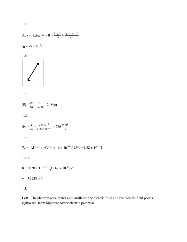
1.a. At x = 1.5m, V = 0 = 𝑘(𝑞1 ) 2.5 + 𝑘(2 𝑥 10−9 ) 1.0 q1 = -5 x 10⁻⁹C 1.b. 1.c. 𝛥𝑉 4𝑉 |E| = 𝛥𝑅 = 0.2𝑚 = 20V/m 1.d. 𝑞 2 𝑥 10−9 ΦE = 𝜀 = 8.85 𝑥 10−12 = 226 0 𝑁·𝑚2 𝐶 1.e.i. W = -ΔU = -q·ΔV = -(1.6 x 10⁻¹⁹)(-8V) = 1.28 x 10⁻¹⁸J 1.e.ii. 1 K = 1.28 x 10-18 = 2(1.67 x 10⁻²⁷)v2 v = 39153 m/s 1.f. Left. The electron accelerates antiparallel to the electric field and the electric field points rightward, from higher to lower electric potential. 2.a. It is the same through both. The circuit forms a single loop and the current is constant throughout that loop. 2.b. It depends upon the resistance of the sample. By Ohm’s law for a common current, the potential difference will be proportional to the resistance. But the relative resistance is unknown for the resistor and wire sample. 2.c. Graph ε - VR on the vertical axis and IR on the horizontal axis. 2.d. 0.35 y = 0.4845x - 0.0028 0.3 Voltage 0.25 0.2 0.15 0.1 0.05 0 0 0.1 0.2 0.3 0.4 Current 2.e. R = 0.48Ω 2.f. 3 0.48 = ρ·𝜋·0.0012 ρ = 5.03 x 10⁻⁷ Ω·m 0.5 0.6 0.7 0.8 2.g.i. Less than. If the ammeter is not ideal, it will have some resistance which will cause a decrease 𝜀 − 𝑉𝑅 in both I and VR. If r = , then r will be greater than the actual value. 𝐼 2.g.ii. Greater than. A non-ideal voltmeter has some less-than-infinite resistance, which decreases the total resistance of the circuit. This allows a greater current to flow through the ammeter. 3.a. Right. 3.b.i. Less than. The counter-clockwise current induced in the loop is out of the page and opposes the initial magnetic field. 3.b.ii. Greater than. The current in the bar to the right creates a magnetic field below the bar which is into the page and aligns with the initial magnetic field. 3.c. M·a = -M·g 𝑑𝑣 𝑑𝑡 + 𝐵2 𝐿2 𝑣 𝑀𝑅 3.d. vT = −𝑀𝑔𝑅 𝐵2 𝐿2 𝐵2 𝐿2 𝑣 𝑅 +g=0 3.e. P= P= 𝜀2 𝑅 = (𝐵𝐿𝑣)2 𝑅 𝑀 2 𝑔2 𝑅 𝐵2 𝐿2 3.f. 𝑑𝑣 𝑑𝑡 + 𝐵2 𝐿2 𝑣 𝑀𝑅 +g=0 Integrate with substitution v= −𝑀𝑔𝑅 𝐵2 𝐿2 𝐵2 𝐿2 (1- 𝑒 − 𝑅𝑀 𝑡 )
