LM5017 Fly-Buck™ Quad/Dual Isolated Supply Evaluation Board
advertisement

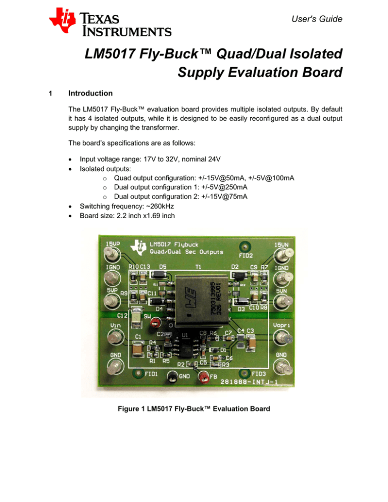
User's Guide LM5017 Fly-Buck™ Quad/Dual Isolated Supply Evaluation Board 1 Introduction The LM5017 Fly-Buck™ evaluation board provides multiple isolated outputs. By default it has 4 isolated outputs, while it is designed to be easily reconfigured as a dual output supply by changing the transformer. The board’s specifications are as follows: • • • • Input voltage range: 17V to 32V, nominal 24V Isolated outputs: o Quad output configuration: +/-15V@50mA, +/-5V@100mA o Dual output configuration 1: +/-5V@250mA o Dual output configuration 2: +/-15V@75mA Switching frequency: ~260kHz Board size: 2.2 inch x1.69 inch Figure 1 LM5017 Fly-Buck™ Evaluation Board 2 Board Connection and Configuration The Vin and GND terminals are the input supply voltage connectors. The isolated outputs appear at the secondary side terminals: 15VP is the +15V output, 15VN is the 15V output, 5VP is the +5V output, 5VN is the -5V output, and two IGND are the isolated ground connectors. To test the board, the electronic load connections should be made as follows: for positive output, the positive terminal of the load should be tied to 15VP (5VP), and the return terminal should be tied to IGND; for negative output, the load’s positive should be tied to IGND, and the return should be tied to 15VN(5VN), and the negative output loads should be isolated to each other and to the positive output load. Figure 2 LM5017 Fly-Buck™ Evaluation Board Top Overlay with Connection Instruction The input voltage range is from 17V to 32V. The max load current is 100mA each for +/5V output and 50mA each for +/-15V output. Within the above operation condition, the overall voltage variation on the output should not exceed 8%. 2.1 +/-5V Dual Output Configuration To reconfigure the board to +/-5V dual output from the quad output, replace the transformer 750313995 with 750314225. The max load current becomes 250mA for +/5V output. 2.2 +/-15V Dual Output Configuration To reconfigure the board to +/-15V dual output from the quad output, replace the transformer 750313995 with 750314226, remove diode D3, D4 and populate the 0Ω resistor R11, R12. The max load current becomes 75mA for +/-15V output.


