SPPL12420EVK Evaluation Kit
2 A, 24 V Synchronous Rectified Step-Down Converter
ADD-ON TO EVK MANUAL: BUCK-BOOST OPERATION
The SPPL12420EVK is an evaluation board designed to demonstrate all of the features and performance of the
SPPL12420RH. The SPPL12420RH is a radiation hardened monolithic synchronous buck regulator featuring integrated
130 mW MOSFETs that provide continuous 2 A output load current.
In the factory-set state the board operates in buck mode. Over a wide 4.5 V to 24 V input voltage range it provides
3.3 V fixed output voltage with very low output ripple. It features an optional EMC input filter (C10, L2) which can be
bypassed. For details refer to the SPPL12420EVK Evaluation Kit User Manual.
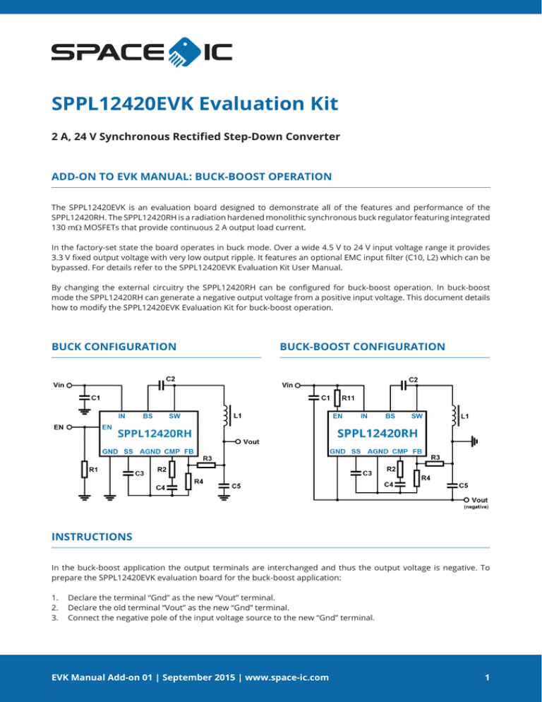
By changing the external circuitry the SPPL12420RH can be configured for buck-boost operation. In buck-boost
mode the SPPL12420RH can generate a negative output voltage from a positive input voltage. This document details
how to modify the SPPL12420EVK Evaluation Kit for buck-boost operation.
BUCK CONFIGURATION
BUCK-BOOST CONFIGURATION
INSTRUCTIONS
In the buck-boost application the output terminals are interchanged and thus the output voltage is negative. To
prepare the SPPL12420EVK evaluation board for the buck-boost application:
1. Declare the terminal “Gnd” as the new “Vout” terminal.
2. Declare the old terminal “Vout” as the new “Gnd” terminal.
3. Connect the negative pole of the input voltage source to the new “Gnd” terminal.
EVK Manual Add-on 01 | September 2015 | www.space-ic.com
1
SPPL12420EVK
2 A, 24 V Synchronous Rectified Step-Down Converter
INSTRUCTIONS (CONTINUED)
4. Activate EN by removing R1 and assemble R11 (100 kOhm), which is a pull-up for permanently active circuit.
Alternatively the terminal EN can be controlled by a voltage source with serial resistor (100 kOhm or higher)
or a voltage divider. To disable the circuit a voltage of ≤ 2 V is needed between the SPPL12420RH component
terminals EN and GND.
(If the circuit is configured for an output voltage between 0 V and -2 V, then a 3.3 V TTL signal can be used to
control the terminal EN without any changes on the circuit.)
Please note for this application:
The SPPL12420RH maximum recommended input voltage VIN of 24 V is related to the sum of the input and output
voltage absolute values: |V(Vin)| + |V(Vout)| ≤ 24 V. E.g. if V(Vout) = -5 V, then V(Vin) ≤ 19 V.
The output voltage value is only limited by the 24 V maximum recommended input voltage VIN of the SPPL12420RH
– not by the input voltage V(Vin). E.g. if V(Vin) ≤ 6 V, then V(Vout) can be set to any value between -0.923 V and -18 V.
NOTE Please consider also the maximum recommended input voltage VIN with respect to Single-Event Effects.
For meaningful voltage measurements at the PCB test points EN, BS, SW, SS, CMP and FB connect the voltmeter
common terminal to Vout (component GND terminal). Also for applying voltages use an isolated voltage source and
connect its negative pole to Vout.
If the EN pull-up resistor is connected to Vin, then the measured input current values always include the additional
current through the pull-up resistor.
For test purposes only, the easiest way to enable and disable the circuit is to control EN by an isolated voltage source
with its negative pole connected to Vout.
IMPORTANT NOTICE
The information contained in this document is believed to be accurate at the time of printing. SPACE IC reserves
the right to make changes to its products or specifications without notice, however, and assumes no responsibility
or liability for the use of its products; nor does the purchase, lease, or use of a product or service from SPACE IC
convey a license under any patent rights, copyrights, trademark rights, or any other of the intellectual rights of
SPACE IC or of third parties. Please visit our website for the most recent revision of this datasheet or contact info@
space-ic.com. Customers are responsible for their products and applications using SPACE IC products.
Resale of SPACE IC products or services with statements different from or beyond the parameters stated by SPACE
IC for that product or service voids all express and any implied warranties for the associated SPACE IC product or
service. SPACE IC is not responsible or liable for any such statements.
© 2015 SPACE IC GmbH. All rights reserved. Information and data in this document are owned by SPACE IC and
may not be edited, reproduced or redistributed in any way without written consent from SPACE IC.
EVK Manual Add-on 01 | September 2015 | www.space-ic.com
2


