AIRFRAME CONTROL NEEDLE ROLLER BEARINGS — ATF, ATL
CONSTRUCTION
DIMENSIONS
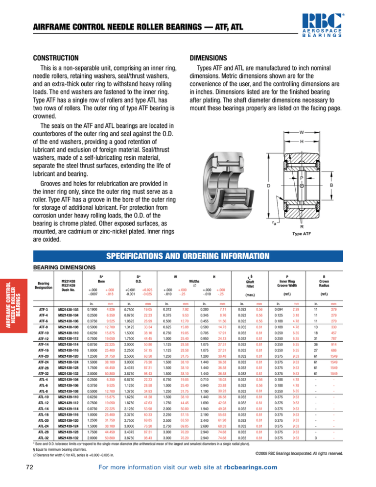
This is a non-separable unit, comprising an inner ring,
needle rollers, retaining washers, seal/thrust washers,
and an extra-thick outer ring to withstand heavy rolling
loads. The end washers are fastened to the inner ring.
Type ATF has a single row of rollers and type ATL has
two rows of rollers. The outer ring of type ATF bearing is
crowned.
The seals on the ATF and ATL bearings are located in
counterbores of the outer ring and seal against the O.D.
of the end washers, providing a good retention of
lubricant and exclusion of foreign material. Seal/thrust
washers, made of a self-lubricating resin material,
separate the steel thrust surfaces, extending the life of
lubricant and bearing.
Grooves and holes for relubrication are provided in
the inner ring only, since the outer ring must serve as a
roller. Type ATF has a groove in the bore of the outer ring
for storage of additional lubricant. For protection from
corrosion under heavy rolling loads, the O.D. of the
bearing is chrome plated. Other exposed surfaces, as
mounted, are cadmium or zinc-nickel plated. Inner rings
are oxided.
Types ATF and ATL are manufactured to inch nominal
dimensions. Metric dimensions shown are for the
convenience of the user, and the controlling dimensions are
in inches. Dimensions listed are for the finished bearing
after plating. The shaft diameter dimensions necessary to
mount these bearings properly are listed on the facing page.
W
H
P
D
B
ra
R
Type ATF
SPECIFICATIONS AND ORDERING INFORMATION
BEARING DIMENSIONS
AIRFRAME CONTROL
NEEDLE ROLLER
BEARINGS
Bearing
Designation
MS21438
MS21439
Dash No.
B*
Bore
+.000
-.0007
W
D*
O.D.
+.000
-.018
+0.001
-0.001
ra §
Shaft
Fillet
P
Inner Ring
Groove Width
R
Crown
Radius
(max.)
(ref.)
(ref.)
H
Widths
∆
+0.025
-0.025
+.000
-.010
+.000
-.25
+.000
-.010
+.000
-.25
in.
mm
in.
mm
in.
mm
in.
mm
in.
mm
in.
mm
in.
mm
ATF-3
MS21438-103
0.1900
4.826
0.7500
19.05
0.312
7.92
0.280
7.11
0.022
0.56
0.094
2.39
11
279
ATF-4
MS21438-104
0.2500
6.350
0.8750
22.23
0.375
9.53
0.345
8.76
0.022
0.56
0.125
3.18
11
279
ATF-6
MS21438-106
0.3750
9.525
1.0625
26.99
0.500
12.70
0.455
11.56
0.022
0.56
0.188
4.78
11
279
ATF-8
MS21438-108
0.5000
12.700
1.3125
33.34
0.625
15.88
0.580
14.73
0.032
0.81
0.188
4.78
13
330
ATF-10
MS21438-110
0.6250
15.875
1.5000
38.10
0.750
19.05
0.705
17.91
0.032
0.81
0.250
6.35
18
457
ATF-12
MS21438-112
0.7500
19.050
1.7500
44.45
1.000
25.40
0.950
24.13
0.032
0.81
0.250
6.35
31
787
ATF-14
MS21438-114
0.8750
22.225
2.0000
50.80
1.125
28.58
1.075
27.31
0.032
0.81
0.250
6.35
36
914
ATF-16
MS21438-116
1.0000
25.400
2.2500
57.15
1.125
28.58
1.075
27.31
0.032
0.81
0.250
6.35
27
686
ATF-20
MS21438-120
1.2500
31.750
2.5000
63.50
1.250
31.75
1.200
30.48
0.032
0.81
0.375
9.53
61
1549
ATF-24
MS21438-124
1.5000
38.100
3.0000
76.20
1.500
38.10
1.440
36.58
0.032
0.81
0.375
9.53
61
1549
ATF-28
MS21438-128
1.7500
44.450
3.4375
87.31
1.500
38.10
1.440
36.58
0.032
0.81
0.375
9.53
61
1549
ATF-32
MS21438-132
2.0000
50.800
3.8750
98.43
1.500
38.10
1.440
36.58
0.032
0.81
0.375
9.53
61
1549
ATL-4
MS21439-104
0.2500
6.350
0.8750
22.23
0.750
19.05
0.710
18.03
0.022
0.56
0.188
4.78
-
-
ATL-6
MS21439-106
0.3750
9.525
1.1250
28.58
1.000
25.40
0.940
23.88
0.022
0.56
0.188
4.78
-
-
ATL-8
MS21439-108
0.5000
12.700
1.3750
34.93
1.250
31.75
1.190
30.23
0.032
0.81
0.250
6.35
-
-
ATL-10
MS21439-110
0.6250
15.875
1.6250
41.28
1.500
38.10
1.440
36.58
0.032
0.81
0.375
9.53
-
-
ATL-12
MS21439-112
0.7500
19.050
1.8750
47.63
1.750
44.45
1.690
42.93
0.032
0.81
0.375
9.53
-
-
ATL-14
MS21439-114
0.8750
22.225
2.1250
53.98
2.000
50.80
1.940
49.28
0.032
0.81
0.375
9.53
-
-
ATL-16
MS21439-116
1.0000
25.400
2.3750
60.33
2.250
57.15
2.190
55.63
0.032
0.81
0.375
9.53
-
-
ATL-20
MS21439-120
1.2500
31.750
2.7500
69.85
2.500
63.50
2.440
61.98
0.032
0.81
0.375
9.53
-
-
ATL-24
MS21439-124
1.5000
38.100
3.0000
76.20
2.750
69.85
2.690
68.33
0.032
0.81
0.375
9.53
-
-
ATL-28
MS21439-128
1.7500
44.450
3.4375
87.31
3.000
76.20
2.940
74.68
0.032
0.81
0.375
9.53
-
-
ATL-32
MS21439-132
2.0000
50.800
3.8750
98.43
3.000
76.20
2.940
74.68
0.032
0.81
0.375
9.53
3
-
* Bore and O.D. tolerance limits correspond to the single mean diameter (the arithmetical mean of the largest and smallest diameters in a single radial plane).
§ Equal to minimum bearing chamfers.
∆ Tolerance for width C for ATL series is +0.000 -0.005 in.
72
©2008 RBC Bearings Incorporated. All rights reserved.
For more information visit our web site at rbcbearings.com
AIRFRAME CONTROL NEEDLE ROLLER BEARINGS — ATF, ATL
MOUNTING
LOAD RATINGS
Types ATF and ATL bearings are designed for heavy rolling
loads. The type ATF bearing is usually clevis mounted or cantilever
mounted on a high strength shaft or bolt. The type ATL bearing
must be straddle-mounted on a high strength shaft or bolt.
The end washers are fastened to the inner ring in a manner
only to maintain the integrity of the assembly while handling
and installing the bearing. Therefore, when mounted they should
be firmly backed up by washers or other clamping surfaces
that are flat and square with the shaft center line. To provide
sufficient washer support, the outside diameter of the clamping
surfaces should be at least as large as the minimum clamping
diameter (da) listed below.
Bearings are constructed to provide maximum
capacity under rolling loads.
The limit load ratings (also called “allowable working
load ratings”) of the bearings are listed below. The
ultimate load ratings are not less then 1.5 times the
limit load ratings. The ultimate load ratings correspond
to 2⁄3 of the Aircraft Static Capacity ratings.
Load ratings are given in pounds-force:
1 lbf = 0.454 kgf = 4.448 N
Before final bearing selection is made, please consult
the RBC Aerospace Engineering Department.
W
H
P
D
da
B
S
ra
T
Type ATL
SPECIFICATIONS AND ORDERING INFORMATION
MOUNTING DIMENSIONS
da
Clamping
Diameter
Weight
Transition Fits
(loose fits)
max.
min.
(approx.)
(minimum)
Transition Fits
(tight range)
max.
min.
Clamping
Force
(minimum)
Bearing Capacity
as a
Track Roller
(CTR)
(max.)
AIRFRAME CONTROL
NEEDLE ROLLER
BEARINGS
S
Shaft Diameters
T
Track
Contact
Width
Limit
Load
Rating
in.
mm
lbs
kgs
in.
in.
in.
in.
in.
mm
lbf
N
lbf
N
lbf
N
-
-
0.030
0.01
0.1894
0.1889
0.1902
0.1897
0.438
11.13
480
2100
900
4000
1200
5300
-
-
0.051
0.02
0.2494
0.2489
0.2502
0.2497
0.516
13.11
870
3900
1430
6400
1910
8500
-
-
0.103
0.05
0.3119
0.3114
0.3127
0.3122
0.672
17.07
2100
9300
2700
12000
3600
16000
-
-
0.187
0.08
0.3744
0.3739
0.3752
0.3747
0.844
21.44
3840
17100
4300
19100
5780
25700
-
-
0.279
0.13
0.4369
0.4364
0.4277
0.4272
0.953
24.21
6150
27400
6400
28500
8530
37900
-
-
0.520
0.24
0.4994
0.4989
0.5002
0.4997
1.109
28.17
8950
39800
10700
47600
14200
63200
-
-
0.749
0.34
0.6244
0.6239
0.6252
0.6247
1.219
30.96
12200
54300
14400
64100
19300
85900
-
-
0.931
0.42
0.7494
0.7489
0.7502
0.7497
1.500
38.10
16300
72500
16400
73000
21800
97000
-
-
1.160
0.53
0.8744
0.8739
0.8752
0.8747
1.625
41.28
25800
114800
18900
84100
25300
112500
-
-
2.360
1.07
0.9994
0.9989
1.0002
0.9997
2.000
50.80
25800
114800
28400
126300
37900
168600
-
-
2.710
1.23
1.2494
1.2488
1.2503
1.2497
2.281
57.94
25800
114800
33500
149000
44600
198400
-
-
3.367
1.53
1.2494
1.2488
1.2503
1.2497
2.562
65.07
25800
114800
36700
163200
48900
217500
-
-
0.107
0.05
0.2494
0.2489
0.2502
0.2497
0.576
14.63
870
3900
2310
10300
3080
13700
0.815
20.70
0.239
0.11
0.3119
0.3114
0.3127
0.3122
0.672
17.07
2100
9300
5370
23900
7130
31700
1.065
27.05
0.437
0.20
0.3744
0.3739
0.3752
0.3747
0.891
22.63
3840
17100
9370
41700
12500
55600
1.315
33.40
0.728
0.33
0.4369
0.4364
0.4377
0.4372
1.109
28.17
6150
27400
15000
66700
19900
88500
1.565
39.75
1.130
0.51
0.4994
0.4989
0.5002
0.4997
1.281
32.54
8950
39800
21400
95200
28500
126800
1.895
48.13
1.630
0.74
0.6244
0.6239
0.6252
0.6247
1.469
37.31
12200
54300
28900
128600
38500
171300
2.045
51.94
2.310
1.05
0.7494
0.7489
0.7502
0.7497
1.578
40.08
16300
72500
33600
149500
44900
199700
2.225
56.52
3.260
1.48
0.8744
0.8739
0.8752
0.8747
1.844
46.84
25800
114800
44600
198400
59500
264700
2.475
62.87
4.330
1.96
0.9994
0.9989
1.0002
0.9997
1.984
50.39
25800
114800
53600
238400
71300
317200
2.685
68.20
6.090
2.76
1.2494
1.2488
1.2503
1.2497
2.281
57.94
25800
114800
69000
306900
92000
409200
2.685
68.20
7.350
3.33
1.2494
1.2488
1.2503
1.2497
2.562
65.07
25800
114800
76000
338100
102000
453700
©2008 RBC Bearings Incorporated. All rights reserved.
For more information visit our web site at rbcbearings.com
73


