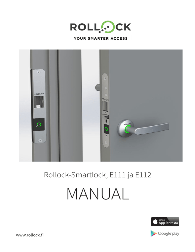
Rollock-Smartlock, E111 ja E112
MANUAL
www.rollock.fi
Table of contents
Table of contents ...............................................................................................................................2
1.Warranty......................................................................................................................................3
2. Important instructions ..............................................................................................................3
3. Technical information ...............................................................................................................6
4.Assembly ....................................................................................................................................6
4.1 Mechanical assembly ................................................................................................................ 6
4.2Schematic .................................................................................................................................. 7
5.
Commisioning of the smartlock ................................................................................................8
5.1 Calibration of the Rollock-lock and the smart strike plate....................................................... 9
5.2 Calibration troubleshooting .................................................................................................... 10
5.2.1
5.2.2
6.
Recovery from calibration faults ..........................................................................................10
Emergency opening from the outside during failed calibration ........................................11
Usage of NFC-tags ....................................................................................................................13
6.1 The Master Key-programming card......................................................................................... 13
6.1.1
6.1.2
6.1.3
Adding access permissions to NFC-tags with the Master Key-programming card.............13
Removing access permissions to NFC-tags with the Master Key -programming card.......14
Removing all passage permissions with the Master Key-programming card ....................15
6.2 Opening the lock with an NFC-tag........................................................................................... 15
7.
8.
9.
Rollock-mobile app..................................................................................................................17
The opening cycle of the lock..................................................................................................17
Problems and troubleshooting ...............................................................................................18
9.1 Problems in opening the lock.................................................................................................. 18
2
Copyright © 2015 Rollock Oy. All rights reserved. • www.rollock.fi
1. Warranty
Rollock Ltd provides the Rollock smartlock a two (2) year warranty. Check the specific information
on the conditions of the warranty on the separate document “The general warranty conditions of
Rollock products”.
2. Important instructions
Improper use of the Rollock smartlock may cause injury to the user and the product. Read this
manual carefully before using the product to avoid damaging the lock. The manual has important
instructions on safety, installation, usage and special situations. Rollock Ltd takes no liability for damages caused by ignoring the safety instructions.
When opening the packaging, make sure to check that there are no clear faults or damage in the lock
or its mechanism to the naked eye. If you notice any damage, do not try to install the lock, but contact your retailer immediately. The Rollock smartlock has electronic components and thus requires
electricity to work.
When installing electrical circuits the following instructions need to be followed:
The lock can be electrified by installing it into a regular electric socket with the special transformer,
sold separately, if one can be found close enough to the lock. Using this form of installment requires no special actions on the part of the user. The Rollock smartlock can also be electrified with a
coupling into the electrical grid, if this connection is done by a trained professional with the required
training, following the legal requirements and regulations.
SAFETY HAZARD! THE ROLLOCK SMARTLOCK CAN BE CONNECTED INTO THE ELECTRICAL GRID WITH A DIRECT
COUPLING (230V) ONLY BY A TECHNICIAN WITH THE REQUIRED TRAINING, WHO KNOWS THE RULES AND
REGULATIONS. ALWAYS HAVE A TRAINED PROFESSIONAL INSTALL ELECTRICAL CONNECTIONS AND COUPLINGS.
INSTALLATIONS DONE BY HOBBYISTS AND UNTRAINED PEOPLE CAN CAUSE HARM TO THE LOCK, AND THE WARRANTY DOES NOT COVER THESE TYPE OF ACCIDENTS. IN ADDITION, UNLICENSED ELECTRICAL CONNECTIONS
MAY CAUSE SERIOUS HARM TO THE USER OF THE LOCK, AND ROLLOCK LTD CANNOT BE HELD ACCOUNTABLE
FOR DAMAGES CAUSED BY IMPROPER INSTALLATIONS BY UNLICENSED PERSONNEL.
The Rollock smartlock is maintenance free. The rotating latch technology employed in the lock
mechanism enables that the lock doesn’t need to be oiled like a traditional mechanical lock; rather it
is harmful to the lock rather than useful. Do not apply any oil to your Rollock-lock!
The Rollock smartlock comes with a Master Key-programming card. This card is paired with your
smartlock during production. You will need the programming card when adding controllers to your
lock (smartphone, tablet) and you can use it to add NFC tags into your lock. The programming card
is twinned specifically to your lock, and it cannot be replaced. In no circumstances should you lose
your programming card!
Copyright © 2015 Rollock Oy. All rights reserved. • www.rollock.fi
3
3. Technical information
Operating voltage:
Power:
Spatial relay:
24V DC STAB (22.8 - 28.8 V)
Median power usage about 4W
Potential free relay start
Max. 30 V AC/DC, 200mA, resistice load 6W
Operating temperature: -25 °C ... +70 °C
Passage time:
15 secons from accepting the BT/NFC -tag
Latch protuberance:
14 mm
Backset:
50 mm
Face plate:
30 mm, brushed finish steel
Latch handedness:
Lock-dependent, separate models for left-handed and right-handed locks
Positions:
Latch deadbolted (latch protruded and door in a shut position)
Latch withdrawn
Indicators:
Green stationary 10 s, door openable
Green blinking 5 s, door openable
Red stationary 5 s, door locked
White stationary, door locked
Power outage:
During a power outage the lock automatically locks itself shut
Width:
2.0 – 5.5 mm (the space between the face plate and the strike plate)
Strike plate:
One type
4. Assembly
4.1 Mechanical assembly
The assembly of the smart strike plate and the physical lock mechanism is done in the way described
in the ”Rollock smartlock assembly instructions” document that comes with the lock.
4.2 Schematic
NOTE! After connecting the couplings the smart strike plate will give a sound signal.
4
Copyright © 2015 Rollock Oy. All rights reserved. • www.rollock.fi
5. Commisioning the smartlock
In the picture below is depicted an assembled Rollock smartlock. The visible parts of the lock are
listed as follows:
1. NFC reader
2. Smart strike plate
3. Inductive power transfer coils
4. Inside handle
5. Rotating latch
6. Assistance latch
7. Day-time operation activator button
8. Indicator light
9. Outside handle
10. Lock mechanism
Picture 1. Rollock –lock assembled
Copyright © 2015 Rollock Oy. All rights reserved. • www.rollock.fi
5
5.1 Calibration of the Rollock-lock and the smart strike plate
The calibration for the power transfer for the Rollock smartlock is done to each lock during commissioning. During the calibration the smart strike plate adjusts the operating voltage of the lock to
required levels and installs the required communication parameters.
NOTE! The door should not be opened during calibration! During the calibration the user
must stay in the room so that the lock can be opened mechanically from the inside handle
in case of calibration failure.
The calibration should be executed by following the instructions below:
1. Make sure that the lock is not in daytime operation mode (Pic 1, part 7), meaning the activator
button in the lock plate is protruded out.
2. Initialize calibration by placing the Master Key-programming card, found inside the Rollock package above the NFC reader of the smart strike plate (Pic 1, part 1.). A sound indication, two beeps,
should be heard.
3. Close the door from the inside. The indicator light around the handle will turn white.
4. When the door closes the smart strike plate will give a new sound indicator.
5. The calibration lasts 20 to 60 seconds, depending on the positioning of the power transfer coils. During the calibration the white LEDs shut off and come back on. The calibration is ready, when the indicator light flashes green three times and the smart strike plate gives a sound indicator. The calibration
can fail if the placement of the induction coils is not correct (part 5.2, calibration troubleshooting).
6. The success of the calibration is tested by opening and closing the door. If the calibration has succeeded, the red LEDs in the indicator light will briefly light up when the door has been closed.
5.2 Calibration trouble shooting
Due to the placement of the smart strike plate and the lock the distance between the inductive power
transfer coils may be too far apart, or the coils are not placed correctly, facing each other. Due to placement faults the operating voltage of the smartlock may not be able to be set to the required levels,
or the communication might not work like intended.
The smart strike plate will inform if the calibration has failed with a beep once every second. The
indicator light around the handle may blink haphazardly or not light up at all.
NOTE! The calibration can be aborted or halted by cutting power to the smart strike plate.
6
Copyright © 2015 Rollock Oy. All rights reserved. • www.rollock.fi
5.2.1 Recovery from calibration faults
Check the positioning of the induction coils, both vertically and horizontally. The door width should
be 2-5,5mm. Horizontally the lock mechanism and the upper and lower ends of the smart strike plate
should be about on the same level.
Picture 2. Width
If the calibration has not been halted by cutting power to the smart strike plate, close the door and
wait for the smart strike plate to try and recalibrate. If the calibration was halted, meaning power was
cut, act according to part 5.1.
Picture 3. Rotating latch locked and door open
If the door is open and the rotating latch (pic 1, part 5) has become locked outwards by pressing
the assistance latch (pic 1, part 6.) the latch can be unlocked by pressing the inside handle and at
the same time pressing the rotating latch back inside. When the door is open and the rotating latch
is locked and protruded, the door should not be closed, and the lock should be disengaged in the
manner described above.
Copyright © 2015 Rollock Oy. All rights reserved. • www.rollock.fi
7
5.2.2 Emergency opening from the outside during failed calibration
When the calibration fails, the emergency opening of the door can be initiated by using the programming card, if you are stuck on the outside and cannot open the door from the inside handle.
1. Initiate emergency opening by flashing the Master Key-programming card over the NFC reader. The
smart strike plate will give a beep
2. After about two (2) minutes the indicator light on the handle shuts off and the lock opens, if the
voltage is sufficient.
3. The lock is openable, when you hear the beep.
NOTE! Do not press the handle before you hear the beep!
4. Open the door.
5. Set the emergency opening off by flashing the Master Key-programming card over the smart strike
plate’s reader (NFC), OR cut the power to the smart strike plate.
6. Check the positioning of the lock mechanism and the smart strike plate.
7. Close the door.
8. The calibration will restart automatically if the power was not cut.
9. If the power was cut, act according to part 5.1 of this manual.
NOTE! The emergency opening may fail if the operating voltage of the lock is not sufficient,
due to the placement of the induction coils! In this situation the only possibility to open the
door is to mechanically break the latch.
The emergency opening will not be possible after a successful calibration!
6. Using the NFC-tags
6.1 The Master Key-programming card
The Master Key-programming card comes with the lock and is paired to the specific lock during
manufac-turing, and it CANNOT be replaced. Never lose your Master Key-programming card, for it
cannot be replaced!
8
Copyright © 2015 Rollock Oy. All rights reserved. • www.rollock.fi
With the programming card the user can:
• Initialize the configuration process during the installation and assembly of the Rollock-lock.
• Add access permissions to NFC tags.
• Remove access permissions from NFC tags.
• Add main users with the Rollock mobile app.
• Remove Bluetooth-twinned items from the Rollock smartlock’s memory.
With the programming card the user cannot:
• Open the smartlock.
6.1.1 Adding access permissions to NFC tags with the programming card
Use the following instructions to add access permissions to NFC tags:
1. Swipe the programming card over the smart strike plate’s NFC reader. The strike plate will give a
beep, the indicator light will turn red and the lock will enter programming mode.
2. Swipe the NFC tag, to which the access permission is to be added, over the strike plate’s NFC reader.
After a successful addition the smart strike plate will give a beep.
3. Repeat part two (2) if you wish to add more tags (max. 251 pcs)
4. Move from programming mode to normal operating mode by swiping the programming card over
the strike plate’s NFC reader. The indicator light will turn white and the lock will move into normal
operating mode.
The smart strike plate will exit programming mode after two (2) minutes of initiating it.
NOTE! Passage permissions can be added only after the smart strike plate and the
smartlock have been successfully calibrated (part 5.1.).
6.1.2 Removing access permissions on NFC tags with the programming card
Use the following instructions to remove access permissions from NFC tags:
1. Swipe the programming card over the smart strike plate’s NFC reader. The strike plate will give a
beep, the indicator light will turn red and the lock will enter programming mode.
2. Swipe the NFC tag from which the access permission is to be removed from over the strike plate’s
NFC reader. After a successful removal the smart strike plate will give a beep.
3. Repeat part two (2) if you wish to remove more tags
4. Move from programming mode to normal operating mode by swiping the programming card over
the strike plate’s NFC reader. The indicator light will turn white and the lock will move into normal
operating mode.
The smart strike plate will exit programming mode after two (2) minutes of initiating it.
Copyright © 2015 Rollock Oy. All rights reserved. • www.rollock.fi
9
6.1.3 Removing all passage permissions from the lock with the programming card
The programming card can be used to remove all access permissions from the lock at once.
The access permissions on all smartphones and tables can be removed as follows:
1. Place the Master Key-programming card above the smart strike plate’s NFC reader.
2. Keep the programming card above the NFC reader continuously for about 30 seconds until the
smart strike plate gives a downward toned sound.
3. Remove the programming card from the NFC reader, unless you want to remove NFC tags as well.
4. The smart strike plate will automatically exit programming mode.
The access permissions on NFC tags can be removed as follows:
1. Place the Master Key-programming card above the smart strike plate’s NFC reader.
2. Keep the programming card above the NFC reader continuously for about 60 seconds. At
about 30 seconds a downward toned sound is heard, and smartphone and tablet access permissions are removed. At 60 seconds a new downward toned sound is heard, and the NFC tag
passage permissions are erased.
3. Remove the programming card from the NFC reader.
4. The smart strike plate will automatically exit programming mode.
6.2 Opening the lock with an NFC-tag
Opening the lock with the NFC tag is done by placing the NFC tag above the NFC reader of the lock.
The smart strike plate will give a short beep when the NFC tag’s code is recognized (part 7.) If the NFC
tag is not equipped with a access permission, the smart strike plate will give two short beeps.
10
Copyright © 2015 Rollock Oy. All rights reserved. • www.rollock.fi
7. Opening cycle of the lock
As the lock receives an order to open from an approved tag, the opening cycle, depicted above, starts:
• The white LEDs in the indicator light turn off.
• The green LEDs light up for 10 seconds, the door is openable.
• The green LEDs blink in the indicator light for five (5) seconds, the door is openable.
• The red LEDs light up in the indicator light for five (5) seconds, the door is locked.
• The white LEDs in the indicator light up, the door is locked.
After opening and re-closing the door the light indicator lights up briefly with red LEDs to indicate that
the door is locked. After this the light turns back into white.
The light indicator turns green after closing the door, if the lock is set to mechanical daytime operation (pic 1, part 7.)
8. The Rollock mobile app
The Rollock smartlock can be operated through a mobile platform (smartphone/tablet) through the
Bluetooth-connection, using the Rollock mobile app. The app is available for iOS-apparatus from the
App Store and to Android-apparatus from Google Play.
The app has extensive instructions to control and use your Rollock-lock.
11
9. Problems and troubleshooting
9.1 Problems in opening the lock
OBSERVATION
REASON
SOLUTION
The smart srtike plate does not
recognize the NFC-tag.
The NFC tag does not have
an access permission programmed.
Check that the tag is the correct
one. Program the tag with an
access permission with the smart
strike plate.
Trying to open the lock with the
Rollock app isn’t working.
The device’s Bluetooth
is not enabled or is not
working.
Restart the Rollock app and Bluetooth on your device.
The lock’s indicator light is red
and there is an opening beep.
The solenoid is not working
as it should.
1. Make sure that the handle is
not pressed down.
2. Restart the lock’s configuration
with the Rollock app if needed.
The lock’s indicator light is
not lighting up and there is no
opening beep.
The lock hasn’t got any
operating voltage or the
current operating voltage is
too low.
Restart the lock’s configuration
with the Rollock app.
The lock does not open with
the Rollock app’s handsfreefunction.
Your device is not within the
area of the lock’s Bluetooth
zone.
Your device’s Bluetooth
is not enabled or is not
working.
1. Check that the device’s Bluetooth is enabled.
2. Place the area into the device’s
Bluetooth zone.
3. Restart your device’s Bluetooth
connection if necessary.
www.rollock.fi


