RETRORAYZ PRO
TM
LED SERIES-SIGNAGE RETROFIT
Light It Up
WARNING
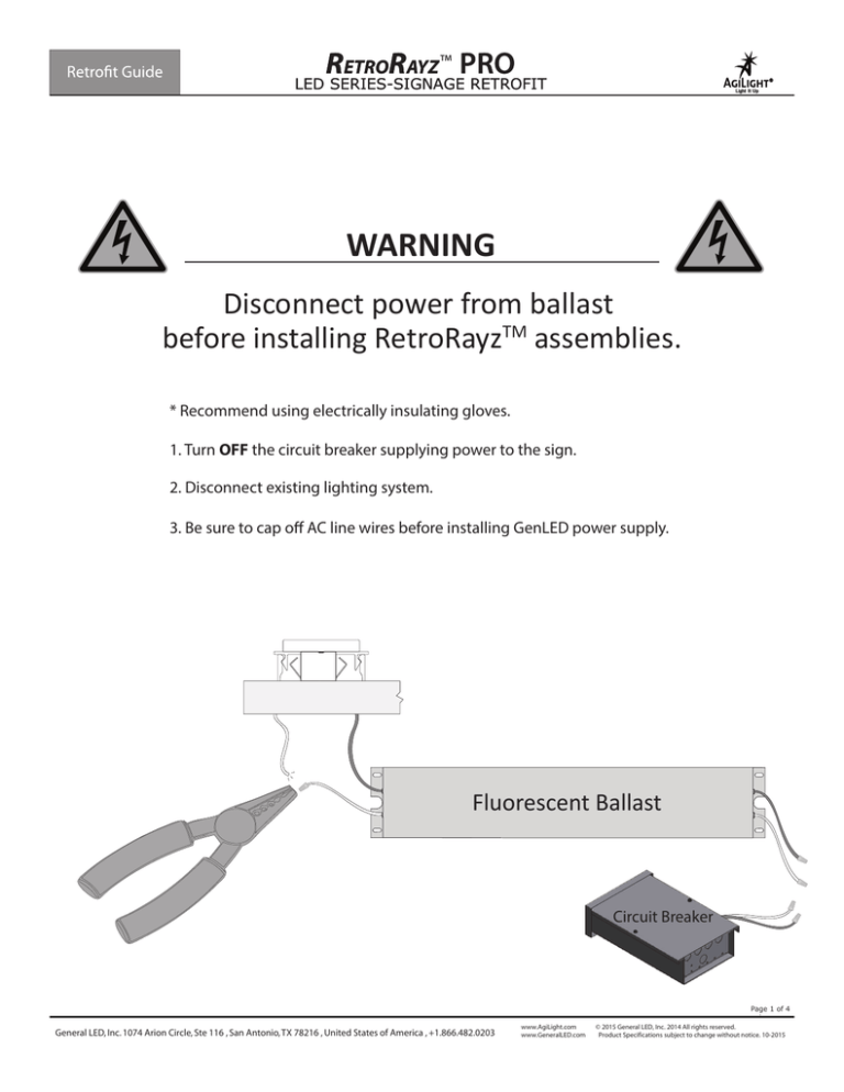
Disconnect power from ballast
before installing RetroRayzTM assemblies.
* Recommend using electrically insulating gloves.
1. Turn OFF the circuit breaker supplying power to the sign.
2. Disconnect existing lighting system.
3. Be sure to cap off AC line wires before installing GenLED power supply.
Fluorescent Ballast
Circuit Breaker
Page 1 of 4
General LED, Inc. 1074 Arion Circle, Ste 116 , San Antonio, TX 78216 , United States of America , +1.866.482.0203
www.AgiLight.com
www.GeneralLED.com
© 2015 General LED, Inc. 2014 All rights reserved.
Product Specifications subject to change without notice. 10-2015
RETRORAYZ PRO LED LightBar
TM
SIGNAGE RETROFIT
Light It Up
Read Instructions Completely Before Installation. Altering The Product In Any Way Voids The Warranty.
WARNING: RISK OF DEATH OR SERIOUS INJURY DUE TO ELECTRIC SHOCK
5
4
ONLY WORKS WITH T8 & T12 RDC SOCKETS
Components:
Tools:
1. General LED PS12-60WSL-100-277V, PS12-60W-100-277V-ENC, or PS12-60W-100-277V
2. AgiLight® RETRORAYZTM PRO LED Light Bar
3. Minimum 18 AWG (0.82mm) wire- (UL Listed)
1.Wire Strippers
2.Screw Driver
3.Tape Measuree
4.Drill
5. Gloves
*Under certain conditions, a heavier gauge wire may be necessary.
4. PLTC Cable- (UL Listed)
5. 22-14 AWG (0.33-2.08mm) wire connectors or
22-18 AWG (0.33-0.82mm) wire nuts, IDC, or butt splice connectors (UL Listed)
* NOTE: Use waterproof wire connectors to maintaing IP68 rating.
6. #8 or #10 (M4 or M5) screws
RETRORAYZ® PRO Installation
RED Safety Cap
RISK OF ELECTRIC SHOCK
1. Turn OFF the circuit breaker
supplying power to the sign.
Disconnect existing lighting system.
before installing GenLED power
supply.
2. Remove existing flouresent lamps,
ballast or non-GenLED power supplies,
and wiring external to raceways.
LEAVE SOCKETS IN PLACE (these will
be used to mount RetroRayz bars).
3. Make sure existing ballast and
ballast wiring has been removed,
ensuring NO POWER to the sockets.
Remove red saftey caps from both
ends of RetroRayz bars.
Sign face
1
LED Modules
2
3
4. Orient RetroRayzTM bars so that LED modules point toward the signs face.
LED optic face to be perpendicular to the ground.
5. Place RetroRayzTM bars into sign according to AgiLight® Population
Density Guide. Insert bar into spring
loaded socket first. Compress spring,
then position opposite side of bar
into socket. Ensure both ends are
securely seated. Remove tape securing
wire to bar.
Page 2 of 4
General LED, Inc. 1074 Arion Circle, Ste 116 , San Antonio, TX 78216 , United States of America , +1.866.482.0203
www.AgiLight.com
www.GeneralLED.com
© 2015 General LED, Inc. 2014 All rights reserved.
Product Specifications subject to change without notice. 10-2015
RETRORAYZ PRO
TM
LED SERIES-SIGNAGE RETROFIT
Light It Up
Mounting Tab
13/16” Threaded Connector
6. Mount power supplies to the sign
and connect power supplies to
RetroRayz bars according to power
supply load label.
*Note: Use IP68 Rated wire connectors to
maintain IP68 raiting of RetroRayz system.
7. Double check all connections and
power supply loading. Connect primary
side of power supplies. Then turn circuit
breaker back on.
WARNING READ BEFORE WIRING
1. Must use General LED’s 12VDC power supply; proper wire gauge to connect to LED modules.
2. Check polarity for DC standard, BLACK (-) to BLACK (-) and RED (+) to WHITE (+).
3. UL 48 Standard requires spacing between power supplies be at least 1 inch (25.4mm) from end to end, and 4 inches (101.6mm) from
side to side.
4. Do not overload power supply and do not use products in submersed applications.
5. Grounding and bonding of the LED power supply must be done in accordance with National Electric Code (NEC) Article 600.
6. Follow all National Electric Codes (NEC) and local codes.
Power Supply Wiring Instructions
AC INPUT (3*AWG #18)
DC OUTPUT (2*AWG #18)
Green=Ground
White=Neutral
Black=Line
Red=Positive (+)
PS12-60WSL-100-277V: Slim 60W Power Supply
PS12-60W-100-277V-ENC: Power Supply With Enclosure
PS12-60W-100-277V: Standard 60W Power Supply
Black=Negative(-)
Maximum LED Light Bars per Power Supply
RetroRayz Nominal 48 - INCH 60 - INCH 72 - INCH 84 - INCH 96 - INCH 108 - INCH 120 - INCH
Bar Length
(1.2m)
(1.5m)
(1.8m)
(2.1m)
(2.4m)
(2.7m)
(3.0m)
Maximum LED
2
1 1/2
1
1
1
2/3
2/3
Light Bars per 60W
Power Supply
Page 3 of 4
General LED, Inc. 1074 Arion Circle, Ste 116 , San Antonio, TX 78216 , United States of America , +1.866.482.0203
www.AgiLight.com
www.GeneralLED.com
© 2015 General LED, Inc. 2014 All rights reserved.
Product Specifications subject to change without notice. 10-2015
RETRORAYZ PRO
TM
LED SERIES-SIGNAGE RETROFIT
Light It Up
Troubleshooting
Problem
Possible Cause
All LED modules are OFF or some of the LED
modules are not illuminated.
1. Power supply may not be over loaded.
2. Wrong Power Supply. Must be 12V DC constant voltage.
3. Bad or loose connections.
Entire section does not light or lights
intermittently.
LED modules icker or appear dim.
1. Bad, loose, or improper connections.
2. Power supplies are spaced too close together; overheating.
*Note: Spacings between LED power supplies shall be at least 1 inch (25.4mm) from
end to end, and 4 inches (101.6mm) from side to side.
1. Power supply may not be properly loaded with LED modules.
2. Power supply may be damaged or defective.
3. Power supply may not be wired correctly. Check AC input wiring
(Green to Ground, Black to BLack, and White to White).
Fixed Socket
Notice: Apply silicone to fixed socket
to prevent bar rotation ensuring
proper sign-face illumination.
Transformer Box Installation (for PS12-60W and PS12-60WSL)
1. Determine desired location for the transformer box.
2. Attach the box to the substrate. Screw through the middle and lower channels.
(When used in a wet location, attach box to a substrate using screws with rubber gasketed heads.)
* The Transformer box is to be attached in all applications with the 13/16” holes always facing down.
3. Using the maximum ½” long self-tapping screw, attach the power supply* to the raised platform.
* See power supply spec sheet for clearances.
4. The bottom of the box has 3 standard 13/16” diameter holes and 2 pilot holes for additional 13/16” holes.
5. Use the middle back 13/16” hole. Attach your metal conduit nipple from the safety disconnect switch box.
It is important that the primary (120 VAC) wires be separated from the secondary (DC) circuit wires completely.
Make all the 120 VAC splices in the safety disconnect box. No excess 120 VAC wiring should be in the transformer box.
* Keep all secondary DC wiring as far away from the primary AC wiring as possible.
** Remember that this location is a dry/damp area. Use the appropriate conduit and strain relief products.
6. Use the included #8 x ½” machine screw as the grounding lug. This lug can be attached to the box
either with the threads and two Green nuts facing the inside of the box or so they face outside the box.
The hole in the bottom of the box between the two 13/16” holes is for the attachment of the grounding lug.
Attach the grounding wires from the LED letters to the box (if grounding of the letters is required).
Place the faceplate on the box, push up under the lip and secure with self-drilling screws to the box.
Page 4 of 4
General LED, Inc. 1074 Arion Circle, Ste 116 , San Antonio, TX 78216 , United States of America , +1.866.482.0203
www.AgiLight.com
www.GeneralLED.com
© 2015 General LED, Inc. 2014 All rights reserved.
Product Specifications subject to change without notice. 10-2015


