TR - 21 - Tramac
advertisement
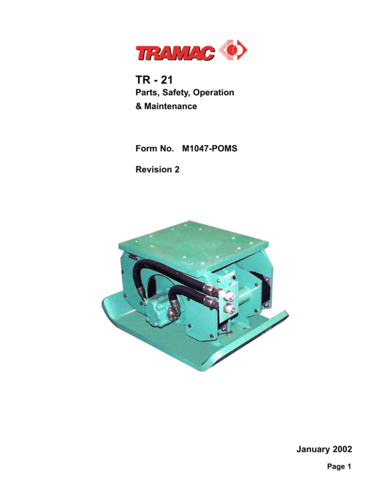
TR - 21 Parts, Safety, Operation & Maintenance Form No. M1047-POMS Revision 2 January 2002 Page 1 TR - 21 Table of Contents Page 2 Forward 3 Technical Specifications 4 Safety S1 Operation O1 Installation I1 Maintenance M1 Troubleshooting T1 Flow Meter Testing F1 Parts P1 Compactor Build Sheet P7 TR - 21 Forward FORWARD You have just acquired a TRAMAC TRAPAC boom mounted vibratory plate compactor. Thank you for your choice. This is the finest equipment of this kind on the market. We are sure it will meet your requirements. This booklet is to provide operation and service instructions necessary for safe and efficient use of the TRAMAC standard model compactor. The use and maintenance of these compactors does not take much time, however, the user should carefully study the following instructions to avoid any damage to the attachment and its carrier. Special attention should be given to the section safety precautions. Should you have any problems in the future, please call your TRAMAC distributor. He will be able to help you promptly. This manual contains information about all the options available on TR-21 compactor, such as: - Flow control version - Standard motor (A, B, C) version - Top mount version - Side plate version, as well as all the combinations of these options. Caution Always use original TRAMAC parts and do not attempt to modify the installation and/or flow setting without the approval of your distributor or your warranty will be voided. Page 3 TR - 21 Technical Specifications Technical specifications Specifications TR - 21TM Centrifugal force classification (lbs) 15000-21500 Centrifugal force classification (kgs) 6804-9752 Frequency (vpm) 2000-2300 Carrier weight (US tons) 10-30 Carrier weight (metric tons) 9-27 Unit weight (lbs) * 1500 Unit weight (kgs) * 680 Height (in) * 26 Height (mm) * 660 Width (in) 23.5 Width (mm) Base plate dimensions (in) 597 23.5 x 32 Base plate dimensions (mm) 597 x 813 * Does not include bracket cap Compactor/carrier requirements Model TR-21 Carrier Carrier min. Compactor motor Maximum compactor Max. compactor flow range hyd. pressure controlled flow range return line pressure (*) operating pressure Flow Control option 30-65 gpm A-motor B-motor 2500 psi 30-34 gpm 250 psi 2300 psi 113-246 lpm 172 bar 113-128 lpm 17 bar 158 bar 30-34 gpm 2500 psi N/A 250 psi 2300 psi 113-128 lpm 172 bar N/A 17 bar 158 bar 40-44 gpm N/A 250 psi 2300 psi N/A 17 bar 158 bar 2500 psi 151-166 lpm 172 bar * WARNING: If the compactor return line pressure exceeds 250 psi (17.2 bar) a 1/4” drain line must be connected from the compactor motor housing drain port to the carrier hydraulic reservoir. If you are unable to obtain the proper hydraulic requirements when installing or adjusting the carrier hydraulic circuit, contact TRAMAC product support for technical support. Page 4 TR - 21 Safety SAFETY PRECAUTIONS Caution Carefully read the following safety precautions. Make sure you fully understand them. Failure to follow a safety warning or recognize and rectify a safety hazard, could result in injury or death to you or others around you. In general, always use common sense in your work habits and keep your tools and equipment in good operating condition. Use trained personnel Allow only trained personnel to operate or service this equipment. Read and understand all safety precautions listed in the TRAMAC manual and in the CARRIER manual. Caution Flying objects or high pressure fluid hazards Do not operate TRAMAC equipment with personnel in the immediate proximity of the equipment because of possible flying objects or high pressure fluid hazards. The operator’s compartment should have the necessary protective guards to prevent entry of flying or Caution falling debris. Wear correct safety protection Verify that all personnel wear protective headgear, eye protection, adequate ear protection and steel toe work boots. In dusty conditions, wear a respirator to protect against dust. Do not wear loose fitting clothing or jewelry while working on the machine. Pay attention to your hands when mounting the compactor Keep your fingers clear when inserting mounting pins. Do not use your fingers to “feel” pin alignment. Unexpected boom or equipment movement could result in painful injury and possible loss of your fingers. Instruct the operator to touch the controls only when instructed. Relieve system pressure prior to working on equipment Escaping fluid under pressure can penetrate the skin causing serious injury. Caution Caution To avoid any risk, be sure to relieve the pressure before disconnecting hydraulic lines. Consult the operator’s manual of the carrier for the proper procedure for relieving pressure. Page S1 TR - 21 Safety Important checkpoints before operation: 1. Tighten all hydraulic fittings before applying pressure. 2. Keep hands and body away from pinholes and nozzles which eject fluid under high pressure. 3. Do not use your hands to search for leaks. Use a piece of paper. Operation and maintenance precautions - Never activate the compactor unless the operator is in full control of the carrier and is seated in the operator’s seat. - Do not operate the compactor above 180º F (82º C) hydraulic oil temperature. - Do not make any alterations to the compactor without authorization from Tramac Product Support department. - Make frequent visual inspections of fasteners, attaching pins, hoses and rubber isolators. - Use caution when torquing fasteners, do not overtorque. Adhere to SAE torque specifications only. A previously overstressed part may fail later. - The major compactor components are heavy. Always use an adequate lifting device. - Never mount the compactor on a carrier that cannot adequately handle the compactor weight. - For nighttime operation, the carrier should offer adequate lighting for safe operation during compacting, repositioning or transporting (European harmonized standard EN-500-1 paragraph 5.1). - Never use the compactor as part of a lifting device. Additional weight could cause the carrier to tip over or cause damage to the compactor components. - Be cautious of flying metal particles when striking any hardened parts with a hand held tool. - Operate the compactor aware of the effects the vibrations may have on trench walls and never operate the compactor in a trench with personnel working nearby in the trench at the same time. - Never service or work on the compactor in an open trench or other unsafe area. - Always clean up oil spills. - Do not over compact near buried utilities or foundations, serious damage to utilities or foundations could result. - Keep personnel clear of the full range of swing, reach, height, depth of carrier boom while operating or positioning the compactor. During standby periods, always lower carrier boom so the compactor rests firmly on the ground and turn off the carrier engine. - Make sure that a window or protective screen is in place on the carrier to fully protect the operator against flying objects. Page S2 TR - 21 Safety Maintain safety decals Always replace any safety or warning decals that become damaged or illegible. Replace all safety or warning decals when repainting the equipment. These decals are available from your TRAMAC dealer or from TRAMAC. Page S3 TR - 21 Operation OPERATION To preserve the life of the compactor and obtain maximum productivity, we urge you to read the following operating and maintenance instructions. Standard operating instructions of the boom mounted vibratory plate compactor Cold weather pre-starting Start up the carrier and circulate the hydraulic oil to warm it up before starting the compactor. Starting the compactor Make sure that the base plate is fully in contact with the soil and down-pressure from the carrier boom has been applied before activating the compactor. Base plate position When compacting, keep the base plate parallel to the ground. Stopping the operation When compaction is complete, shut off hydraulic motor before lifting it from the ground. Sensitive procedures Make sure to properly adjust the down pressure force. Down pressure force which is too light will weaken the contact between the plate and the material. Consequently, the vibrations will not adequately transmit through the soil (producing low efficiency). Also, when insufficient down pressure is applied, the vibrations created by the compactor, instead of being sent into the soil, will be transmitted up to the boom and into the carrier causing excessive rattling and shaking which can lead to premature wear on the carrier. If this rattling occurs, apply a little more down pressure. On the other hand, it is necessary to find a medium between not enough and too much down pressure. Excessive down pressure force will stretch the rubber isolators beyond their limits and shorten their life. Page O1 TR - 21 Operation The shear of the rubber isolators should not exceed 1 - 1/2” (38.1 mm) Avoid metal to metal contact Caution Avoid a metal to metal contact between the base plate and the upper bracket assembly. This occurs with too much down pressure. The sound it makes is a warning to ease up on down pressure. Avoid “ironing,” “smoothing” or “side-loading.” “Ironing,” “smoothing” or “side-loading is not recommended as it can be detrimental to the life of the rubber isolators. Caution Operating instructions for compaction Number of passes Best results are usually obtained with two passes. For the initial pass, the time required for each position is only as long as visible compaction is apparent. The second pass should be done with greater down pressure force. Our experience has shown that within 20 - 30 seconds the maximum compaction effect will be achieved for each placement. Additional compaction time may be detrimenttal both, to the compactor and to the compactor efficiency, since the soil will escape laterally creating holes. Depth of layers TRAMAC compactors can achieve 95% modified Proctor density in lifts whose maximum depth can range up to 48” (1219.2 mm). The above figures are theoretical and the best results will be obtained by making initial tests to determine the proper lift depth and speed to achieve the required density. Caution Variables affecting the operation Soil type As a general rule, the finer the soil particles are, the more difficult the compaction is. Moisture content The moisture acts as a lubricant between soil particles. However, too much moisture will saturate the soil with water taking up space which would normally be filled by soil particles. Frequency of the compactor The best frequency of the compactor depends on two conditions: - The lower the frequency (i.e. the lower the rpm of the motor), the lower the centrifugal force applied to the soil. - Each soil type has its own resonant frequency for which the efficiency is the best when the centrifugal force is fixed. Page O2 TR - 21 Operation Down pressure Applied by the carrier boom, down pressure keeps the compactor in contact with the soil and allows a good energy transfer to the soil. Down pressure is also responsible for a part of the compaction. COMPACTION What is compaction? Compaction is a process of applying energy to loose soil, in order to consolidate it and remove any void spaces. With compaction, soil particles are rearranged closer to each other and the air or water trapped between these particles is forced out. This increases the density and consequently its load - bearing capacity. Three major methods are used to compact soil: STATIC FORCE: Compaction is achieved using a heavy machine (for example, a static roller), whose weight squeezes soil particles together without the presence of vibratory motion. IMPACT FORCE: Compaction comes from a ramming shoe alternately striking and leaving the ground at a high speed, literally ‘kneading’ the ground to increase its density. VIBRATION: Compaction is achieved by applying a high frequency vibration to the soil. Page O3 TR - 21 Operation Two main factors govern the extent to which the soil can be compacted: - The soil (its nature, mechanical properties and moisture content) - The method of compaction The soil Types of soil Soils are divided into 5 basic types which break into two groups, cohesive and non - cohesive materials (see tables below). The cohesive soils (any material with a high clay content) have the characteristic of sticking together. * AASHTO stands for American Association of State Highways and Transportation Officials. * ASTM stands for American Society of Testing and Materials. These different soils have various mechanical properties, which require different compaction processes and induce different results. Page O4 TR - 21 Operation Moisture content In acting as a lubricant between soil particles, moisture is a critical factor in the compactibility of a soil. - Too little moisture will not allow soil particles to move into a dense arrangement. - Too much moisture will saturate a soil, taking up space which would normally be filled by soil particles. Page O5 TR - 21 Operation Vibratory compaction Methods of compaction according to soils Granular soils are best compacted by vibration. This is because the vibration action reduces the frictional forces at the contact surfaces, thus allowing the particles to move freely under their own weight. This settling action and repositioning of particles is known as vibratory compaction. All the air voids that were previously present in the soil mass are now replaced by solidly packed soil. Cohesive soils are best compacted by impact force. Thus, a combination of impact force and vibration is needed and TRAMAC compactors combine static weight with vibration to achieve compaction. Page O6 TR - 21 Operation The vibration method The function of TRAMAC compactors is based on the use of vibrations in combination with static down pressure force to achieve compaction. The creation of vibrations The heart of each compactor is an eccentric shaft which produces the vibratory action. The eccentric shaft is a body which rotates around any axis other than one at its center of mass. As the eccentric shaft rotates, it exerts an outward force (the centrifugal force), which is directed in a 360º pattern. This enables the compactor to stay in the same spot. The total vertical distance that the vibrating base plate travels is called the amplitude. It is a direct function of the applied weight and also depends on the soil. The frequency and amplitude of a machine will predetermine its most effective application. The transmission of vibrations The compaction effort is measured by the dynamic force generated, which depends on the frequency amplitude, the properties of the soil, the down pressure of the carrier boom, the weight of the compactor, and especially the centrifugal force. NOTE: The less the vibrations are transmitted to the carrier, the more efficient the compaction will be. Rubber isolators are used to isolate the main frame from the vibrating plate. Page O7 TR - 21 Operation The soil reactions Each load cycle of the vibratory compactor generates a stress wave which decreases intensity as it travels further from the vibrating plate. Each wave characteristic is dependent upon the properties of the soil. Various soils will react differently when subjected to vibration (see table below). The purpose of vibration is to set the soil particles into a state of motion almost as fluid. The soil is broken down and subjected to shear between the particles as the material is gradually rearranged during compaction. The movement of soil will be greatest when the vibratory plate is operating closest to the natural frequency of the vibrator - soil system. Note: Many parameters are involved in the efficiency of the compaction of a given soil type and TRAMAC compactors are designed and built to adapt to most of them. There is no formula to calculate production of the compactor. After a short trial you will determine the necessary depth of lifts, down pressure applied by the carrier, oil flow supplied to the compactor and duration of compactor on the same spot to achieve the best efficiency. Operating instructions when used as a pile driver The compactor may be used to drive piles or posts. In this case, an adapter assembly must be devised and attached to the compactor. Caution Do not weld the adapter directly to the base plate. When welding, excessive heat may distort the eccentric housing and you may permanently damage the unit. The base plate has been specially drilled to secure such adapter assemblies. When operating, make sure that the post or the pile is properly secured to the adapter. For example, cut a hole in the pile and, with a chain or steel cable bind it securely to the adapter. Make sure that all precautions have been taken when using the compactor. When moving the pile or the post, conditions may be very dangerous for surrounding workers. Caution Page O8 TR - 21 Installation FLOW CONTROL VALVE TYPICAL HYDRAULIC HOOK UP CARRIER PUMP CARRIER AND/OR TRAMAC FILTER RESERVOIR CARRIER VALVEBANK TRAMAC FC VALVE CARRIER SERVICE SPOOL P T EF COMPACTOR CARRIER COOLER CF OPTIONAL DRAIN LINE COMPACTOR INSTALLATION If it is a top mount compactor, attach bracket cap to the compactor upper mounting frame, install mounting bolts, apply LOCTITE # 271 THREADLOCKER or equivalent to bolt threads, install nuts and torque to specifications. Mount compactor to carrier. Start the carrier and rotate compactor with the bucket circuit to the fully extended OUT position. Measure hose length required to connect compactor to the carrier. Hose specifications must be sufficient to withstand the compactor maximum rated hydraulic operating pressure. Caution Page I1 TR - 21 Installation Connect one compactor hose to the carrier HP SUPPLY connection. Connect the other compactor hose to the carrier LP RETURN connection. If flow control present, connect compactor HP inlet hose to the FLOW CONTROL VALVE PORT STAMPED “P” and connect the opposite hose end to carrier HP SUPPLY connection. Connect compactor LP outlet hose to FLOW CONTROL VALVE PORT STAMPED “T” and connect the opposite end to carrier LP RETURN connection. Start carrier and rotate compactor with the bucket circuit to the full extended OUT and full retracted IN position and check for unobstructed hose movement. A one-way check valve must be installed between the carrier and the compactor return hose on double acting two-way circuits. This will prevent accidental reverse of the hydraulic flow Caution to the compactor motor. Check the eccentric housing for correct EP 80-90 oil level. Page I2 TR - 21 Maintenance MAINTENANCE INSTRUCTIONS DAILY MAINTENANCE Hydraulic motor and eccentric housing Check the motor and housing for oil leaks. Mounting Check compactor bracket cap attachment bolts/nuts, carrier dipperstick attachment pins/bushings and quick-attach devices for proper fit to the compactor. Make sure that the pin retainers are secured in place. Hand lubricate pins and bushings with grease. Hydraulic fittings and hoses Check all hoses for damage and connections for leaks. Rubber isolators Check the rubber isolators for tightness and damage. NEVER OPERATE THE COMPACTOR WITH ANY LOOSE OR DAMAGED RUBBER ISOLATORS! Page M1 TR - 21 Maintenance PERIODIC MAINTENANCE NOTE: TRAMAC compactor eccentric shaft bearings do not have grease fittings that require frequent lubrication. The eccentric shaft bearings are automatically lubricated by splash lubricating EP 80 - 90 gear oil. Oil level The oil level should be checked weekly or every 40 operating hours. To check, place the compactor on a level surface. Clean dirt from the eccentric housing lower DRAIN plug area. Remove DRAIN plug and check to see if oil level is showing at the bottom of the eccentric housing lower drain hole. If oil level is low, clean dirt from the eccentric housing upper VENT/FILL plug. Remove the upper eccentric housing VENT/FILL plug and add only enough EP 80 - 90 gear oil until it appears at the bottom of the drain hole, reinstall both plugs. CAUTION: Do not overfill the eccentric housing. Too much oil can cause excessive “drag” on the eccentric shaft and overload the compactor motor and carrier hydraulic system. CAUTION: If the eccentric housing gear oil level is found substantially overfilled, it is an indication the compactor hydraulic motor seal has failed and allowing carrier hydraulic oil to transfer into the eccentric housing. Do not continue to operate the compactor until the defective motor seal or complete motor has been replaced. The eccentric housing must be drained and serviced with new EP 80 - 90 gear oil. Gear oil change After the first 100 hours from the initial installation, the factory fill eccentric housing gear oil should be changed (and every 6 months thereafter). To drain gear oil, clean dirt from the eccentric housing lower DRAIN plug and eccentric housing upper VENT/FILL plug and remove both plugs. Tilt compactor and drain gear oil out the lower drain hole into a suitable container. CAUTION: Gear oil should be examined for metal contamination. If metal contamination is found, flush the eccentric housing with clean solvent before refilling with new gear oil. If not, the eccentric shaft bearings may be damaged. Refill the compactor with new EP 80 - 90 gear oil and reinstall both plugs. Page M2 TR - 21 Troubleshooting Hydraulic circuit Like any hydraulic machine, it is important to verify that the oil flow delivered by the carrier conforms to the flow requirements of the compactor. Refer to the manual of the carrier for proper maintenance of the carrier, i.e. changing of the filter element, checking of the flow delivered by the carrier to the attachment, checking of relief valve setting, etc. Caution Proper flow is very important because: - If flow supplied to the compactor exceeds the range of the compactor model used, the bearings and motor life will be shortened. - If flow supplied to the compactor is under the range of the compactor model used, the compactor will vibrate erratically and may damage the boom or the boom cylinders of the carrier. Hydraulic oil Contaminated hydraulic oil may damage both your TRAMAC attachment and the hydraulic system of the carrier. Make sure to check the filter periodically and to change its cartridges when needed. Take special care to keep all hose ends and couplers clean and free of dirt when changing attachment. Caution Page T1 Oil temperature plays an important role as excessively hot oil increases internal leakage which then lowers efficiency and damages the seals. TR - 21 Troubleshooting TECHNICAL PROBLEMS Some of the following checks must be performed by a skilled technician. Contact the service department of your TRAMAC dealer. Caution COMPACTOR DOES NOT VIBRATE PROBABLE CAUSE SOLUTION PUMP IN THE CARRIER CHECK THE PUMP WITH A FLOW METER. REPAIR OR REPLACE IF NECESSARY. RELIEF VALVE IN THE CARRIER CHECK THE RELIEF VALVE PRESSURE SETTING. ADJUST, REPAIR OR REPLACE IF NECESSARY. FLOW CONTROL VALVE IN THE COMPACTOR CIRCUIT WITH A FLOW METER, CHECK THE COMPACTOR MOTOR FLOW. HYDRAULIC MOTOR REMOVE MOTOR AND CHECK FOR STRIPPED MOTOR SLINES OR STRIPPED ECCENTRIC SHAFT SPLINES. ECCENTRIC SHAFT BEARINGS REMOVE MOTOR AND TURN ECCENTRIC SHAFT BY HAND. THE BEARINGS ARE GOOD IF IT TURNS SMOOTHLY. IF IT TURNS HARD OR DOES NOT TURN AT ALL, BOTH BEARINGS MUST BE INSPECTED FOR DAMAGE. HOSE CONNECTIONS INSURE THAT HOSES ARE CONNECTED TO THE PROPER PARTS. MAKE SURE THAT THE BALL SHUT-OFF VALVES OR QUICK COUPLERS ARE OPEN AND NOT DEFECTIVE. COMPACTOR VIBRATES ERRATICALLY PROBABLE CAUSE SOLUTION LOW FLOW CHECK CARIER HP CIRCUIT FLOW WITH A FLOW METER AND ADJUST/REPAIR AS NECESSARY. IF APPLICABLE, CHECK HP FLOW FROM THE COMPACTOR FLOW CONTROL VALVE PORT CF TO THE COMPACTOR MOTOR AND REPAIR AS NECESSARY. BROKEN SHOCK MOUNTS VISUALLY CHECK RUBBER ISOLATORS AND REPLACE AS NECESSARY. MOUNTING PINS/BUSHINGS CHECK MOUNTING PINS/BUSHINGS FOR PROPER SIZE LOOSE OR EXCESS WEAR. REPLACE AS NECESSARY. Page T2 TR - 21 Troubleshooting EXCESSIVE OIL LEAK AT VENT/FILL PLUG PROBABLE CAUSE SOLUTION MOTOR SEAL FAILURE IF THERE IS HYDRAULIC OIL IN THE ECCENTRIC HOUSING, REMOVE MOTOR AND REPLACE SHAFT SEAL OR REPLACE COMPLETE MOTOR ASSEMBLY. CHECK MOTOR RETURN CIRCUIT TO THE CARRIER RESERVOIR FOR HIGH BACK PRESSURE OBSTRUCTION. BEARING FAILURE PROBABLE CAUSE SOLUTION HIGH FLOW EXCESSIVE FLOW CAN CAUSE MOTOR TO SPEED UP AND DAMAGE THE BEARINGS. SEE PROCEDURE "HOW TO CHECK FLOW TO MOTOR." OIL LEVEL LOW CHECK OIL LEVEL IN ECCENTRIC HOUSING AND REFILL AS NECESSARY. THE FULL MARK IS THE LOWER ECCENTRIC HOUSING DRAIN PLUG HOLE. CONTAMINATED OIL CHECK OIL IN ECCENTRIC HOUSING FOR DARK, DIRTY OIL OR METAL IN IT. DRAIN OIL, CLEAN ECCENTRIC HOUSING AND REFILL WITH CLEAN OIL. LOOSE BOLTS PROBABLE CAUSE Page T3 SOLUTION BOLTS NOT TORQUED TO PROPER SPECIFICATIONS RETORQUE BOLTS LOCTITE NOT USED USE LOCTITE # 271 THREAD LOCKER OR EQUIVALENT TR - 21 Troubleshooting Eccentric shaft bearing removal and installation TO REMOVE: Drain gear oil out of the eccentric housing and remove hydraulic motor. Remove cap screws from bearing housing. NOTE: The bearing housing is secured to the eccentric housing with silicone “gasketing” sealant. Two 3/4” NC threaded jacking holes are provided in the bearing housing to aid in removal. Install two 3/4” NC x 1 - 1/2” (or 3/4” NC x 1 - 1/4”) cap screws into the jacking holes and tighten until the bearing housing is free from the eccentric housing. Remove snap ring from the eccentric shaft and slide out shaft from the bearing housing. Bearing can be pressed out of the housing with a standard press. TO INSTALL: Clean all parts before assembling. Press bearing into bearing housing. Insert SPLINE end of eccentric shaft into bearing housing and install snap ring on the shaft. Lubricate bearing with gear oil. Apply a generous bead of ULTRA BLUE RTV SILICONE LOCTITE # 587 “gasketing” sealant or equivalent around bearing housing mounting surface and install on eccentric housing. Clean bearing housing mounting cap screws and apply LOCTITE # 271 THREADLOCKER or equivalent to cap screws, install and torque to specifications. Press bearing into bearing housing. Lubricate bearing with gear oil. Apply a generous bead of ULTRA BLUE RTV SILICONE LOCTITE # 587 “gasketing” sealant or equivalent around bearing housing mounting surface and install on eccentric housing. Clean bearing housing mounting cap screws and apply LOCTITE # 271 THREADLOCKER or equivalent to cap screws, install and torque to specifications. NOTE: Make sure the eccentric shaft turns freely without binding. Install hydraulic motor and refill eccentric housing with gear oil. Rubber isolator removal and installation TO REMOVE: To remove one rubber isolator, remove 8 nuts and cap screws from upper mounting frame and eccentric housing. Pry and tap the rubber isolator until it is removed. To remove all four rubber isolators, support the upper mounting assembly with a suitable hoist, forklift, crane or carrier and remove all 32 nuts and cap screws. Pry and tap the rubber isolators to remove. TO INSTALL: Position rubber isolator(s) in between the upper mounting frame and eccentric housing, align cap screw holes, install cap screws. Clean nut and cap screw threads, apply LOCTITE # 271 THREADLOCKER or equivalent to cap screws and torque to specifications. Page T4 TR - 21 Flow Meter Testing FLOW METER TEST PROCEDURE How to check the carrier hydraulic circuit Mount a flow meter in place of the compactor. Also mount a low pressure (0 - 600 psi) gauge on the outlet of the flow meter in order to test the back pressure in the return circuit. With the flow meter in place, activate the circuit and bring the machine up to operating temperature 120º F - 130º F (49º C - 54º C). Do not test the machine cold. WARNING: If the control valve is equipped with a solenoid, switch on the solenoid before starting the engine to avoid damages to the flow meter. Do not switch the solenoid on or off when the engine is running. Adjust the flow output to match the requirements of the compactor. Page F1 TR - 21 Flow Meter Testing After the flow has been adjusted, load flow meter to the compactor operating pressure value plus 600 psi (27.6 bar). If necessary, readjust flow to keep the compactor flow value constant for pressure varying between 1000 psi (69 bar) and compactor operating pressure value (see TECHNICAL SPECIFICATIONS) plus 600 psi (27.6 bar). Mount the low pressure (0 - 600 psi) gauge on the flow meter outlet to check the return oil back pressure. WARNING: If the return line pressure exceeds 250 psi (17.2 bar), a 1/4” drain line must be connected from the compactor motor housing drain port to the carrier hydraulic reservoir. If you are unable to obtain the proper hydraulic requirements when installing or adjusting the carreir hydraulic circuit, contact TRAMAC product support for technical support. How to check FC flow to motor Disconnect the hose from the FC flow control valve port stamped CF. Connect this hose to the IN port of the flow meter. Connect a hose from flow meter OUTLET to the FC valve tee fitting stamped “T”. With the flow meter in place, activate circuit and bring the carrier hydraulic oil up to operating temperature 120º F - 130º F (49º C - 54º C). Do not test the flow with cold oil. WARNING: If the control valve is equipped with a solenoid, switch on the solenoid before starting the engine to avoid damages to the flow meter. Do not switch the solenoid on or off when the engine is running. Adjust the flow output to match the requirements of the compactor. CARRIER PUMP CARRIER AND/OR TRAMAC FILTER RESERVOIR CARRIER VALVEBANK TRAMAC FC VALVE CARRIER SERVICE SPOOL P T EF CARRIER COOLER CF IN OUT FLOW METER Page F2 TR - 21 Flow Meter Testing Load the flow meter to 2300 psi (159 bars) and observe GPM (LPM) output. The flow range should be within the specifications. If the flow reads too low or too high, remove and inspect the flow control cartridge for damaged or missing external o-rings, missing orifice or orifice retaining snap ring. NOTE: Flow control cartridges are non-adjustable, however flow can be varied by changing the orifice size (make sure that the proper orifice is in place). Replacement of the cartridge will be necessary if replaced external o-rings, orifice and/or snap ring, do not correct the flow to specifications. FC FLOW CONTROL VALVES ORIFICE-VARIABLE CARTRIDGE FC 45 NON-ADJUSTABLE CARTRIDGE FC-65 NON-ADJUSTABLE CARTRIDGE FC-125 (Make sure that FC-125 is set to 3900 psi when you order) Page F3 TR - 21 Page Left Blank Intentionally Page F4 TR - 21 Parts Page P1 TR - 21 Parts Item Part Number 1 2 4 5 6 7 8 9 10 11 12 13 14 15 16 17 18 19 20 21 22 588 - 801 588 - 801 588 - 207 588 - 207 PAC - 6 588 - 208 PAC - 87 PAC - 22 PAC - 8 PAC - 3 PAC - 4 PAC - 203 588 - 801 PAC - 204 588 - 801 PAC - 205 588 - 801 PAC - 206 2082 - 6S SFV - 06 PAC - 23 21 09 11 05 01 10 06 01 Qty. 1 1 1 1 2 1 4 32 1 4 4 2 2 12 12 2 4 2 1 1 32 DESCRIPTION Upper frame Lower frame Rear cap (bearing housing) Front cap (motor side)(bearing housing) Bearing Eccentric shaft Shock absorber 1/2" NC x 2" lg Cap screw gr. 8 Snap ring 1/2" NC x 1-1/2" lg Cap screw gr. 8 1/2" Flat washer 1/2" NC x 1" lg Cap screw gr. 8 Flat washer 7/8" NF x 2-1/2" lg Cap screw gr. 8 Flat washer 3/4" NC x 1-1/4" lg Cap screw gr. 8 Flat washer 3/4" NC x 1-1/2" lg Cap screw gr. 8 Pipe plug Vent plug 1/2" NC nut Page P2 TR - 21 Parts ARRANGEMENT WITHOUT FLOW CONTROL VALVE Page P3 TR - 21 Parts Item Part Number 1 2 3 4 5 2042 - 16 - 16S 960955 960956 2062 - 16 - 12S M - 50A M - 50B 2082 - 4S 391 - 2883 - 119 6 7 Qty. 2 1 1 3 1 1 1 1 DESCRIPTION Bulk head Low pressure hose High pressure hose Fittings A-motor B-motor Motor drain plug Motor shaft seal Page P4 TR - 21 Parts FLOW CONTROL VALVE ARRANGEMENT Page P5 TR - 21 Parts Item Part Number 1 3 4 5 6 7 8 9 10 11 12 13 FC - 65 - 32 960957 960958 960959 960960 2042 - 16 - 16S 2062 - 16 - 12S 202702 - 16 - 16S 203101 - 16 - 16S M - 50A 2082 - 4S 391 - 2883 - 119 Qty. 1 1 1 1 1 2 3 2 1 1 1 1 DESCRIPTION Flow control valve High pressure hose Low pressure hose Low pressure hose High pressure hose Bulk head Fittings Fittings Fitting A-motor Motor drain plug Motor shaft seal Page P6 COMPACTOR BUILD SHEET TRAMAC Corporation provides the following Compactor Build Sheet in order to meet all the possible compactor design combinations required by the customer. From the following options, please select the unit and features that best suit your needs: Model CHOOSE ONE OPTION Side TM Plate CHOOSE ONE OPTION FC Valve (A Motor only) No FC Valve CHOOSE ONE OPTION A Motor B Motor TR-9 TR-14 N/A N/A TR-21 TR-40 C Motor CHOOSE ONE OPTION Flange Fittings N/A SAE Oring Fittings N/A N/A N/A N/A N/A N/A N/A Page P7
