Signal Interface
MAP Series
protection. The supply input,
measurement input and RS 232
interface are all equipped with
special interference suppressor filters.
Custom-tailored configuration
While the basic versions support
a comprehensive range of applications, five other configurations
are available to provide additional
options.
Tare function
Special features
Description
• process-controlled indicator
with digital display
• precision 0.01%
• scope of measurement range
-9,999...+40,000
• adaptation of potentiometric
sensors
• adaptation of active sensors
with standardized output signal
• up to 32 meas. per second
• tare function
• max. 4 programmable
limiting value comparators
• peak memory
• programming inhibit function
• communication via logic inputs
and outputs
• RS 232 interface
• analog output function with
standardized signals
• integrated auxiliary power supply for active sensors
• CE mark
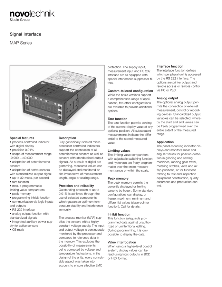
Fully galvanically-isolated microprocessor-controlled indicators
support the connection of all
potentiometric sensors as well as
sensors with standardized output
signals. As a result of digital programming, measured values can
be displayed and monitored onsite irrespective of measurement
length, angle or scaling range.
Precision and reliability
Outstanding precision of up to
0.01% is achieved through the
use of selected components
which guarantee optimum temperature stability and interference
immunity.
The process monitor (MAP) supplies the sensors with a highly
constant voltage supply. The input
and output voltage is continuously
monitored by the processor and
compared to reference data in
the memory. This excludes the
possibility of measurements
being corrupted by voltage and
temperature fluctuations. In the
design of the units, every conceivable aspect was taken into
account to ensure effective EMC
The tare function permits zeroing
of the current display value at any
optional position. All subsequent
measurements indicate the differential to the stored measured
value.
Limiting values
The limiting value comparators
with adjustable switching function
and hysteresis are freely programmable over the entire measurement range or within the scale.
Peak memory
The peak memory permits the
currently displayed or limiting
value to be frozen. Some standard
configurations can display, or
freeze, maximum, minimum and
differential values (slave-pointer
function). Call for details.
Inhibit function
This function safeguards programmed data against unauthorized or unintentional editing.
During programming, it is only
possible to display the data.
Value interrogation
When using a higher-level control
system, display values can be
read using logic outputs in BCD
or HEX format.
Interface function
The interface function defines
which peripheral unit is accessed
by the RS 232 interface. The
options are printer output and
remote access or remote control
via PC or PLC.
Analog output
The optional analog output permits the connection of external
measurement, control or recording devices. Standardized output
variables can be selected, whereby the start and end values can
be freely programmed over the
entire extent of the measured
range.
Application
The panel-mounting indicator displays and monitors linear and
angular values for position detection in grinding and sawing
machines, running gear travel,
metering strokes, valve and air
flap positions, or for functions
relating to test and inspection
equipment construction, quality
assurance and production control.
Novotechnik U.S., Inc.
155 Northboro Road
Southborough, MA 01772
Phone:
Fax:
Email:
Basic version
Type designations
Scope of measurement range
Upgraded
version
Intelligent
version
508-485-2244
508-485-2430
info@novotechnik.com
Full version
MAP330
MAP340
MAP332
MAP342
MAP334
MAP344
MAP444
-2,000...
+2,000
-9,999...
+20,000
-2,000...
+2,000
-9,999...
+20,000
-4,000...
+4,000
-9,999...
+20,000
-9,999...
+40,000
Measurement rate /sec.
1...16
1...16
1...16
1...16
1...32
1...16
1...16
Auxiliary voltage
•
•
•
•
•
•
•
Tare function
•
•
•
•
•
•
•
Limiting values
0
0
2
2
4
4
4
Peak memory
•
•
•
Programming inhibit function
•
•
•
Digital output BCD/Hex
•
•
•
Interface RS232
•
•
•
Option
Option
Option
Analog output
Option
Measurement input
Optional potentiometric or active input (current or voltage)
[MAP330/340/332/342]
Voltage supply
Standard 230 VAC (optional feature 115 VAC or 24 VDC)
Option
Option
Option
Supplementary option potentiometric
and active input (current) [MAP334/344]
Potentiometric
and active input
(current and voltage)
[MAP444]
• = Included in delivery
Other models on request
Technical Data
Technical Data
Voltage supply
230 VAC, 50/60 Hz, 6 VA
115 VAC 50/60 Hz, 6 VA
24 VDC, 0.5 A; (20...30 VDC)
Display
5 digit LED-measured value display, 14 mm high
1 digit LED programming unit display, 7 mm high
Scope of
measurement range
MAP330/332
MAP334
MAP340/342/344
MAP444
-2000...+2000
-4000...+4000
-9999...+20000
-9999...+40000
Precision
MAP330/322
MAP334
MAP340/342/344
MAP444
0.05%,
0.03%,
0.01%,
0.01%,
Measurement rate
Standard
MAP334
1/2/4/8/16 meas./s
1/2/4/8/16/32 meas./s
Temperature coefficient
MAP330/332/334
MAP340/342/344
MAP444
50 ppm/°C
20 ppm/°C
20 ppm/°C
Control inputs
MAP330/340
MAP332/342
MAP334/344/444
2 x 20-30 V /typ. 5 mA
2 x 20-30 V /typ. 5 mA
4 x 20-30 V /typ. 5 mA
programmable functions
Comparator
MAP332/342
MAP334/344/444
2-fold limiting value comparator
4-fold limiting value comparator
Relay output
only in versions
with limiting values
2 x changeover contact 250 V max./
1A limiting value output
Optocoupler output
MAP334/344
MAP444
4 x logic outputs max. 50 V/30 mA
for limiting values or value interrogation
±1
±1
±1
±1
Digit
Digit
Digit
Digit
Measurement inputs
MAP330/340
MAP332/342
MAP334/344
MAP444
Standard: potentiometer or 0(4)…20 mA
or 0...10 V
Standard: potentiometer and 0(4)...20 mA
or 0...10 V and 0(4)…20 mA
Interface
MAP334/344
MAP444
RS 232
Auxiliary voltage output
24 VDC, 70 mA non-stabilized
No-load voltage max. 30 VDC
Protection class
IP 00 at terminals, IP 40 at front of housing to DIN 40050
Analog outputs
(supplementary option
MAP444)
0...10 V/ 0...20 mA/ 4...20 mA; resolution 0.05%
Current output: burden impedance max. 400 Ω
Voltage output, load impedance min. 10 kΩ
Ambient temperature
0...50°C
Dimensions
Housing
Recess measurements
H48 x W96 x D135 mm
H92 x W45
Terminal
screw-type, plugable
Subject to changes
© February 2007
Novotechnik U.S., Inc. All rights reserved.
Terminal diagram
Relay
Outputs
Control
Inputs
Terminal assignment
1 Supply voltage AC (L) or DC (+)
2 Supply voltage AC (N) or DC (-)
3 Not assigned
4 Common terminal limiting values
5 Break contact output
limiting value 1
6 Make contact output
limiting value 1
7 Break contact output
limiting value 2
8 Make contact output
limiting value 2
9 Not assigned
10 Control input 4
11 Control input 3
12 Control input 2
13 Control input 1
14 Auxiliary supply output 24 V (+)
15 Auxiliary supply output 24 V (-)
(common terminal control inputs)
21 Shielding RS 232
22 GND interface RS 232
23 TXD interface RS 232
24 RXD interface RS 232
25 Reference potential (+V inp.) for
optocoupler outputs
26 Optocoupler outputs 4 (MSB)
27 Optocoupler outputs 3
28 Optocoupler outputs 2
29 Optocoupler outputs 1 (LSB)
31 Sensor terminal 3
32 Measurement input or DMS33 Sensor terminal 2 or DMS+
34 Measurement input voltage
(f.e. 0...10 VDC)
35 Measurement input current
(f.e. 0...20 mA DC)
36 Sensor terminal 1 or 0 V
37 0 V
38 Analog output
39 Shielding fo measurement input
and analog output
Novotechnik U.S., Inc.
155 Northboro Road
Southborough, MA 01772
Phone:
Fax:
Email:
508-485-2244
508-485-2430
info@novotechnik.com
Dimensions
Order designations
Analog output
1 = 0...10 VDC
4 = 0 (4)...20 mA
Voltage supply
1 = 230 VAC, 50/60 Hz
2 = 110 VAC, 50/60 Hz
8 = 24 VDC
M A P
Series
•
-
-
A
Type
330, 332, 340, 342
Measurement input
PO = potentiometric
IC = 0 (4)...20 mA
IV = 0...10 VDC
334, 344, 444
PC = potentiometric or current
0 (4)...20 mA (programmable)
VC = 0...10 VDC or
0 (4)...20 mA (programmable)
Subject to changes
© February 2007
Novotechnik U.S., Inc. All rights reserved.


