DC/DC Converters: The Step up (Boost) Converter Covered in
advertisement

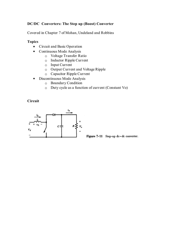
DC/DC Converters: The Step up (Boost) Converter Covered in Chapter 7 of Mohan, Undeland and Robbins Topics Circuit and Basic Operation Continuous Mode Analysis o Voltage Transfer Ratio o Inductor Ripple Current o Input Current o Output Current and Voltage Ripple o Capacitor Ripple Current Discontinuous Mode Analysis o Boundary Condition o Duty cycle as a function of current (Constant Vo) Circuit Continuous Mode Boost Converter Waveforms Switch D.Ts (1-D).Ts On Off Ts time vL Vd Vo time Vd-Vo iL IL IL time IDiode IL Average = Io time Continuous Mode Boost Converter Relationships (You must be able to derive) Vd Voltage Transfer Ratio: Vo (1 D ) Inductor Peak to Peak Ripple Current: Input Current I d IL IL Vd .D.Ts L Io (1 D ) Diode Current: Peak to Peak Ripple = I L IL 2 IL Peak to Peak Output Voltage Ripple (approximation) = Io (1 D ) I o .esr (1 D ) Ripple Current Rating of the Output Capacitor Electrolytic capacitors have a maximum ripple current rating and the output capacitor of the boost converter is exposed to high ripple. The easiest way to determine the required ripple rating of the output capacitor is to use the following relationships, which hold for any waveform: Ts 0 I rms Ts Ts I dc I 2 (t).dt 0 I rms I (t).dt Ts I dc2 I ac2 I dc 2 I rms I ac2 Use the general formula for rms to calculate the rms of the diode current waveform and assume that the ac component of this goes into the capacitor while the dc component flows into the load. Note if the inductor ripple is 20% or less then it can safely be neglected when calculating the capacitor current. If we neglect inductor ripple then the diode current components become: ( I diode ) rms ( I diode ) dc ( I diode ) ac I L. 1 D I L .(1 D ) ( I diode ) 2rms ( I diode ) 2dc Discontinuous Mode Boundary Just as in the Boost case the boundary condition for discontinuous mode occurs when the average inductor current IL is half of the inductor peak-to-peak ripple IL. IL 2 Boundary occurs at I L but the output current I o so at the boundary I o I oB Vd .D.Ts Vo .D.(1 D ).Ts 2L 2L I d (1 D ) I L (1 D ) Vo .D (1 D ) 2 Ts 2L Behaviour of Boost Converter in discontinuous mode As in the buck converter discontinuous mode operation results in a higher than expected output voltage for a given duty cycle. Conversely the duty cycle must be reduced in order to maintain a given input to output voltage ration when the converter goes into discontinuous mode. Problem You are required to design a boost converter to provide a constant 300V output from a Fuel cell stack. Fuel cell stack parameters: Maximum Load: 50Amps No Load Voltage: 100V Full Load Voltage: 60V at 50Amps The following design constraints are to be adhered to: You may assume that the switch and diode are ideal but a switching frequency of 50kHz is to be used. -The peak-to-peak inductor ripple current must not exceed 10% of the inductors dc current rating. -A number of 350V/1000uF capacitors are available and the minimum number of these should be used for the output capacitance. The capacitors have the following specifications: Voltage: 350V max Capacitance: 1000uF +/-10% Ripple current rating: 4 Amps maximum esr: 0.4 maximum The converter is to be controlled by an integrated circuit control chip which is capable of generating duty cycles in the range of 0.1 to 0.9 In discontinuous operation the boost converter characteristic is: D 2 I o L Vo TsVd Vd 1 1. Calculate the inductor value and current rating required. 2. Determine the amount of output capacitance required and worst-case output voltage ripple 3. Determine the value of dummy load required to prevent overvoltage.


