450
ACTA ELECTROTEHNICA
Modelling and Simulation of Static VAr
Compensator (SVC) in Power System
Studies by MATLAB
Houari BOUDJELLA, Fatima Zohra GHERBI and Fatiha LAKDJA
Abstract: This paper presents the modelling and simulation of Static Var Compensator (SVC) in power
system studies by MATLAB. In the first step, we have modeled mathematically with MathCAD how to
analyze the rating of SVC. In second step, we have conferred modelling of SVC in power system to analyze
its behaviour operating with in control range and outside of control range and how to perform power
system studies which is anchored with load flow analysis for SVC realization. In the third step, we have
been modelling separately the SVC transfer functions with open control loop in the respective control
elements: measuring module, thyristor susceptance control module and voltage regulator module, and we
have used lag/led compensators theories to configure open and close loop transfer function with respective
gain/phase margin. At the final step, we have controlled the voltage and the reactive power transit in the
power system, by SVC device.
Keywords: FACTS, SVC, Var and Voltage Control.
1. INTRODUCTION
The SVC is a shunt device of the FACTS
family using power electronics to control
power flow and improve transient stability on
power grids. Has been used for reactive power
compensation since the mid 1970, firstly for
arc furnace flicker compensation and then in
power transmission systems. One of the first
40 Mvar SVC was installed at the Shannon
Substation of the Minnesota Power and Light
system in 1978. The SVC results in the
following benefits
• Voltage support, and regulation,
• Transient stability improvement, and
• Power system oscillation damping,
• Reactive power compensation,
• Power transfer capacity increase and line
loss minimization.
Controlled reactive compensation in
electric power system is usually achieved with
the following configuration corridors.
Thyristor Controlled reactor (TCR), fixed
capacitor
(FC),
Thyristor
switched
© 2008 – Mediamira Science Publisher. All rights reserved.
capacitor/reactor (TSC/TSR) and mechanical
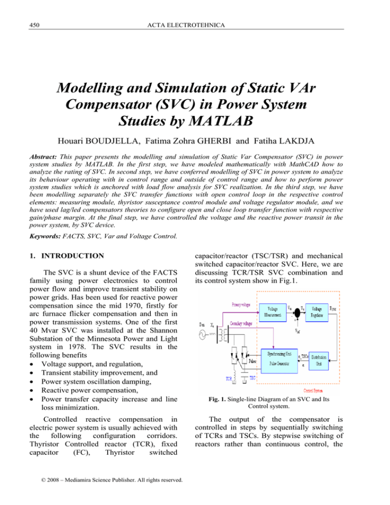
switched capacitor/reactor SVC. Here, we are
discussing TCR/TSR SVC combination and
its control system show in Fig.1.
Fig. 1. Single-line Diagram of an SVC and Its
Control system.
The output of the compensator is
controlled in steps by sequentially switching
of TCRs and TSCs. By stepwise switching of
reactors rather than continuous control, the
Volume 49, Number 4, 2008
need for harmonics filtering as part of the
compensator scheme is eliminated.
X L rated =
2. SVC MATHEMATICAL MODEL
WITH MATHCAD
X transf
The following example shows how the
parameters of the SVC can be determined.
Assume the SVC comprising of one 109MVAr TCR bank and three 94 MVAr TSC
banks connected to the 735 kV bus via a 333
MVA, 735/16 kV transformer on the
secondary side with the leakage reactance of
the transformer (Xk=15%). The voltage drop
of the regulator is 0.01pu/100VA (0.03pu/300
VA). When the SVC operating point changes
from fully capacitive to fully inductive, the
SVC voltage varies between 1 - 0.03 = 0.97
p.u and 1+ 0.01 = 1.01 p.u.
The SVC rating is as follows:
QTSC = 3 . 94 Mvar , QTCR = 109 Mvar ,
a). At rated line-to-line voltage Urated, the
nominal inductive and capacitive currents
of SVC referred to primary side are
determined as follows:
Q L rated = 3 U rated . I L rated = U 2rated . B Lrated (1)
I Lrated =
Q Lrated
3 U rated
=
Q 3 TSC − Q TCR
3 U rated
451
2
U rated
S
Q L rated
=
16 2
= 2.348 Ω
109
2
U rated
16 2
= 0.15.
=
= 0.115 Ω
Ptrans 333
X L TCR (Δ ) = X L rated − X transf = 2 . 233 Ω (5)
X L TCR (1Φ ) = 3 . 2.233 = 6.67 Ω
L L TCR =
6.67
= 17 .7 mH
2.π .60
X C rated =
C=
2
U rated
Q C rated
=
16 2
= 0 . 9078 Ω (6)
282
1
= 2.92 m F
2.π .60.0.9078
3. SVC V-I CHARACTERISTICS
The
steady-state
and
dynamic
characteristics of SVCs describe the variation
of SVC bus voltage with SVC current or
reactive power, Fig.2 illustrates the terminal
voltage-SVC current characteristic with
specific slope.
ΔVC max ΔVL max
(7)
Slope =
=
IC max
I L max
= 135.89 A
Q C rated = 3 U rated . I C rated = U 2rated . B C rated (2)
I C rated =
QC rated
3 U rated
=
Q3 TSC
3 U rated
= 221.51 A
b). At the maximum line-to-line voltage
Umax=742.35 kV
2
QL max = 3U max .I L max = U max
.B Lrated
I L max = I L rated
U
max
U rated
c). At the minimum
Umin=712.95 kV
= 137 .24 A
line-to-line
(3)
voltage
2
QC min = 3U min .I C min = U min
.BC rated (4)
I C min = I C
rated
U min
= 214 .86 A
U rated
d). The reactive of the TCR and TSC are
calculated as
Fig. 2. SVC steady-state control characteristics.
-
The regulation slope allows:
To extend the linear operating range of the
compensator.
To improve the stability of the voltage
regulation loop.
ACTA ELECTROTEHNICA
452
-
To enforce automatic load sharing between
static var compensator as well as other
voltage regulation devices.
The V-I characteristic is described by the
following three equations:
V = V ref + X S . I
(8)
SVC is in regulation rang;
I
V=
− BC max
(9)
generations and loss. The power flow studies
related to SVC applications are:
- Determine the location and preliminary
rating of the SVC.
- To render information on the effects of the
SVC on the system voltages and power
flows.
- To provide the initial condition for system
transient analysis.
- And operating boundaries likewise inside
or outside control range.
SVC is fully capacitive B = BC max ;
V=
I
B L max
4.2. SVC Operating within the control
range
(10)
SVC is fully inductive B = BL max .
The voltage at which SVC neither absorbs
nor generates reactive power is the reference
voltage Vref see in figure (2). In practical this
voltage can adjusted within the typical range
of ±10%. The slope of the characteristics
reflects a change in voltage with compensator
current and, therefore can be considered as
slope reactance XSL, resulting the SVC
response to the voltage variation.
4. MODELING OF STATIC VAR
COMPENSATOR IN POWER
SYSTEM STUDIES
The control range of the SVC is defined
as:
I min ⟨ I SVC ⟨ I max ..... Vmin ⟨ V ⟨Vmax
In this range, SVC is represented as a PVnode (generator node) at an auxiliary bus with
P=0, V =Vref. A reactance of equivalent to the
slope the V-I characteristics is added between
the auxiliary node and the node of coupling to
the system. The node at the point of common
coupling is a PQ node with P=0, Q=0, as show
in Fig.3:
(a)
PQ node: p=0,
(b)
SVC
d
I-SVC
jXSL
SVC
application
studies
require
appropriate power system models and study
methods covering the particular problems to
be solved by the SVC application. The
following studies normally are required for an
SVC application from the early planning stage
till operation.
• Load flow studies.
• Small and large disturbance studies.
• Harmonic studies.
• Electromagnetic transient studies.
• Fault studies.
4.1. Model for load flow analysis
The main objective of load flow analyses
is to determine the node voltages reactive and
active power flow in the network branches,
PQ node: p=0,
PV node
P=0, V=Vref
SVC
jB
Auxiliary
node
Fig. 3. SVC model for operation, a) within the
control range, b) outside the control rage
5. SVC CONTROL TRANSFER
FUNCTION MODELED BY MATLAB
The SVC modelling comprises of
following elements:
- The voltage and current measuring (and
filtering) circuit.
- A regulator including possible additional
signals fed to the reference point.
- Additional control signals are used for
system damping improvement.
- A distribution unit.
Volume 49, Number 4, 2008
-
A model of the Thyristor susceptance
control module.
A model of the interface with the power
system.
In SVC model, the characteristics of the
measuring and filter circuit can be
approximated by transfer function as given
below:
Voltage
or
Current
1
s Tm + 1
For this example Ki = 300.
5.3. Thyristor susceptance control model
e − s Td
s Tb + 1
Bref
5.1. Measuring module
Vmeans
Imeans
The measuring circuit time constant is
0.001-0.005s.
453
B
Td is the gating delay or (dead time) is
neglected as it is very small (≈ 1/12 th cycle of
the fundamental) and Tb is the effect of
Thyristor firing sequence control.
The compensator susceptance, BSVC is
given by:
B 0 (B TSC + B TCR )
BSVC
(11)
B 0 + B TSC + B TCR
Where B0 is
transformer.
the
susceptance
of
the
Fig. 4. Measuring model.
5.2. Measuring module
B max
Verror
KI
s
B ref
B min
Fig. 6. Susceptance control model.
5.4. Distribution unit module
The function of a distribution module is to
determine the number of TSC units and the
level of TCR reactive power absorption (or a
combination of both) based on the required
BSVC
Bref
Fig. 5. Voltage Regulator Model integral type.
Fig. 7. Distribution unit model for TSR-TSC type
SVC.
454
ACTA ELECTROTEHNICA
reactive power. For SVC with continuous
output, there is not a need to model this
module. Fig.7 shows a distribution model for
TSR-TSC SVCs.
6. TYPICAL PARAMETERS FOR SVC
MODELS
The parameters of the SVC have to be
selected to SVC rating and performance
criteria taking into account the power system
behavior under various operating conditions.
To improve SVC strategic operation these
parameters are viable.
Table 1: Typical Parameters for SVC Model.
Module Parameter
Definition
Typical value
For time
Measuring
Tm
0.001-0.005s
Constant
Gating delay
0.001s
Thyristor
Td
Firing delay 0.003-0.006s
Control
Tb
Ki can be
Voltage
Integrator gain
Ki
adjusted
regulator
Steady-state
Slope
XSL
0.01-0.05 p.u
error
Module Parameter
Definition
Typical value
For time
Measuring
Tm
0.001-0.005s
Constant
7. SIMPLIFIED TRANSFER CONTROL
FUNCTION OF SVC
The system stability studies narrate how
to get the substantial results by means of SVC
to stabilize system voltages. For this situation
the power system is represented by a source
voltage in series with an equivalent system
reactance Xe in p.u. Fig.8 show a simplified
block diagram of the SVC with closed-lope
terminal voltage control.
1
: transfer function of the
1 + sTm
voltage measuring device.
K SL
GR ( s) =
: transfer function of voltage
1 + sT
regulator and slope unit.
1
GB (s) =
: transfer function of the
1 + sTd
compensator main circuit.
G N ( s ) = X e : transfer function of the network.
H ( s) =
The
slope
of
the
steady-state
characteristics is related to transfer function
1
.
gain K SL =
X SL
For simplified model, we have:
G R ( s)G B ( s)G N ( s)
ΔVT ( s) =
ΔVref ( s)
1 + G R ( s)G B ( s)G N ( s) H ( s)
+
1
ΔV s ( s)
1 + G R ( s)G B ( s)G N ( s) H ( s)
(12)
7.1. SVC Model example
This example shows how to control SVC
model for determination of the SVC node
voltage variation due to a small disturbance.
Qrated=180 Mvar,
power system SC= 1800 MVA, XSL= 2%.
Tm=0.003s, T=0.02s, Td = 0.001s.
7.2. SVC Plant Designing
Effect of voltage regulation and slope
with transfer function:
K SL
GR ( s) =
1 + sT
K SL =
1
X SL
= 50 p .u .
SVC transfer function of voltage
measuring device outcomes is given by Fig.4.
Fig. 8. Simplified block diagram of SVC.
In the simplified model:
H (s) =
1
1 + sTm
455
Volume 49, Number 4, 2008
Ess
( s → 0)
=
1
1
ΔVT ( s )
=
=
= 0.17
ΔVS ( s) 1 + X SL X e 1 + 50 × 0.1
(15)
This means that the variation of voltage in
the SVC node is equivalent to 17% of the
variation of the source voltage.
8. LOCATION OF AN SVC
Fig. 9. Effect of voltage regulation and slope.
7.3. SVC Control Compensator
Designing
GB (s) =
1
1 + sTd
Fig. 10. Compensator main circuit.
On the base of SVC rating, we have:
Q
180
(13)
X e = rated =
= 0.1 p.u.
SC
1800
Suppose that the Δ Vref = 0 the response
of the system to a step-like voltage Δ Vs is
formulated as:
ΔVT ( s)
1
(14)
=
ΔV S ( s ) 1 + G R ( s)G B ( s )G N ( s ) H ( s )
In the steady-state (s → 0 ) :
Location of an SVC strongly affects
controllability of the swing modes. In general
the best location is at a point where voltage
swings are greatest. Normally, the mid-point
of a transmission line between the two areas is
a good candidate for placement.
9. PRINCIPLE OF SVC OPERATION
Thyristor Controlled Reactor (TCR): is a
fixed reactor in series with bidirectional
Thyristor valve. The amplitude of the TCR
current can be changed continuously by
varying the Thyristor firing angle from 90° to
180°. The TCR firing angle can be fully
changed within one cycle of the fundamental
frequency, thus providing smooth and fast
control of reactive power supply to the system.
Thyristor Switched Capacitor (TSC):
comprises of a capacitor in series with
bidirectional Thyristor valve and a damping
reactor, used to switch on and off the capacitor
bank. The TSC can operate in coordination
with the TCR so that the sum of the reactive
power from the TSC and the TCR becomes
linear.
10. EFFECT OF AN SVC LOCATION IN
TRANSMISSION LINE
We take the example of the paragraph
(§.2), after simulation by Matlab, we have
obtained the waveforms of the SVC:
The SVC equivalent susceptance seen
from the primary side can be varied
continuously from -1.04 p.u/100 MVA (fully
inductive) to +3.04 p.u/100 MVAr (fully
capacitive). This susceptance is the image of
the reactive power of SVC compensator.
Initially the source voltage is set at 1.004
p.u, resulting in a 1.0 p.u voltage at SVC
456
ACTA ELECTROTEHNICA
(a)
(a)
Voltage & Current of Pos.Seq
alpha TCR (degree)
Va (pu) Ia (pu/100MVA)
Va
Ia
2
1
0
-1
150
140
130
120
110
100
0.1
0.2
0.3
0.4
0.5
0.6
0.7
0.8
0.9
1
0.1
0.2
0.4
0.5
0.6
0.7
0.8
Time (s)
Numbers of TSCs
1.02
1
0.98
0.96
1
n TSCs
3
Vref
Vm
1.04
0.9
Numbers of the TSCs in service
Vairation of the primary voltage
2
1
0
0.94
0
0.92
0.9
0.3
(b
1.06
Vref (p.u)
Vm (p.u)
160
0
0
(b)
0
(c)
0.1
0.2
0.3
0.4
0.5
0.6
0.7
0.8
0.9
0.1
0.2
0.3
0.4
Primary susceptance controled by the SVC compensator
0.5
0.6
0.7
0.8
0.9
1
Times (s)
1
Fig. 12. Signals command generated by the SVC
control system.
3
2.5
B svc (p.u/100 MVA)
alpha TCR
170
90
-2
-3
Bsvc
2
1.5
1
0.5
0
-0.5
-1
-1.5
0
0.1
0.2
0.3
0.4
0.5
0.6
0.7
0.8
0.9
1
Reactive power absorbed & injected in power system by SVC
(d)
Firing angle-alpha (degree)
180
3
TCR absorbs approximately 40% of its
nominal reactive power (α = 94°).
Finally, at t=0.8 s the voltage is increased
to 1.0 p.u and the SVC reactive power is
reduced to zero.
300
Q svc
250
11. CONCLUSIONS
Q (Mvar)
200
150
100
50
0
-50
-100
-150
0
0.1
0.2
0.3
0.4
0.5
0.6
0.7
0.8
0.9
1
Times (s)
Fig. 11. Simulation of the dynamic response of the
SVC.
terminals when the SVC is out of service
(fig.11.b). The SVC is initially floating (zero
Current). This operating point is obtained with
TSC1 in service and TCR almost at full
conduction, α = 96° (fig.12.a).
At t=0.1s voltage is suddenly increased to
1.025 p.u. The SVC reacts by absorbing
reactive power Q=-95 MVAr (fig.11.d) to
bring the voltage back to 1.01 p.u.
The 95% settling time is approximately
135 ms. At this point all TSCs are out of
service (fig.12.b) and the TCR is almost at full
conduction α = 94° (fig.12.a).
At t = 0.4 s the source voltage is suddenly
lowered to 0.93 p.u The SVC reacts by
generating 256 Mvar of reactive power, thus
increasing the voltage to 0.974 p.u. At this
point the three TSCs are in service and the
In this article, we have modeled the small
disturbances including control action, resulting
in the determination of the required rating of
SVC for the given subject matter.
Furthermore, it has also determined the
appropriate control signal for adequate
transient stability as well as control structures
corridors to give most viable and composite
perception of the SVC control system.
Therefore, the power system stability
describes the voltage control at the point of
SVC connection to the system. This technique
may be used to verify the adequacy of the
control parameters. And finally, we connect an
SVC on a power grid to control the voltage
and the reactive power.
REFERENCES
1. Acha. E, Esquivel. C.R.F, Perez. H.A, Camacho.
C.A (2004): FACTS modelling and simulation in
power system Networks. 421pp. Chap 2. John
Wiley & Sons Ltd, British Library.
2. Acha. E, Agelidis. V.G, Anaya-Lara. O, Miller.
T.J.E (2002): Power Electronic Control in
Volume 49, Number 4, 2008
3.
4.
5.
6.
7.
8.
9.
Electrical Systems” 451pp. Chap 6 & 9. Newnes
Publisher.
Xiao-Ping. Z, Rehtanz. C, Bikash. P (2006):
Flexible AC Transmission Systems: Modelling and
Control. 395pp. Chap.2, Springer Berlin
Heidelberg New York.
Ambriz- P´erez. H, E. Acha, C. R. Fuerte-Esquivel
(2000): Advanced SVC Models for NewtonRaphson Load Flow and Newton Optimal Power
Flow Studies. IEEE Transactions on Power
Systems.
Chi. W.J, Wu. C.J (1992): Voltage profile correction
of a load bus by static reactive power compensators
with contization controllers. Electric Power System
Research, PP 47-58.
Gérin –Lajole.L, G.Scott, S. Breault, E.V. Larsen,
D.H. Baker and A.F. Imece (1990): Hydro -Québec
Multiple SVC Application Control Stability Study.
IEEE Transactions on Power Delivery, pp .15431551.
Hubbi. W, Hiyama. T (1998): Placement of static
var compensator to minimize power system losses.
Electric Power Systems Research, PP 95-99.
Lin. C.E, Chen. T.C, Huang. C.L (1988): Optimal
control of a static var compensator for
minimization of line loss. Electric Power Systems
Research, PP 51-61.
Noroozian. M (1996): Modelling of SVC power
system studies. ABB Power Systems Division,
information NR500-026E, Sweden.
457
10. Boudjella. H (2008): Contrôle des puissance
réactive et des tension sur un réseau de transport
au moyen de dispositifs SVC. Mémoire de magister,
université de Sidi Bel Abbes, Algérie.
11. Gherbi. F.Z.I (2004): Contribution a l’étude de la
répartition économique des puissances actives et
réactives dans un réseau d’énergie électrique.
Thèse de doctorat d’état, UDL, Sidi Bel Abbes,
Algérie.
12. Lakdja. F (2005): Contrôle des transits de puissance
par dispositifs FACTS: Application à un réseau
d’énergie électrique. Mémoire de magister,
ENSET, Oran, Algérie.
Houari BOUDJELLA
Fatima Zohra GHERBI
Intelligent Control and Electrical Power System
Laboratory
University of Sidi-Bel-Abbes, Algeria
(e-mail: boudj_h@yahoo.fr)
Fatiha LAKDJA
Department of Electrical Engineering
University of Saida, Algeria
e-mail: flakdja@yahoo.fr

