Unit05 - Matthieu Benoit
advertisement

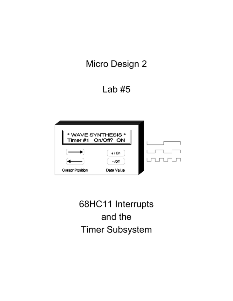
Micro Design 2 Lab #5 68HC11 Interrupts and the Timer Subsystem Introduction The immense benefits of having the HC11's timer facilities may not seem obvious at first. You are already familiar with software delays such as the one in your DELAY subroutine. It has been employed when displaying information to a human on the LED, PIA Test Board and the LCD. It was also called upon in the PIA switch debouncing lab. Simply replacing those delay loops with a programmable timer doing the same job will provide no benefit unless there is something else that the CPU could be doing and some way of allowing the CPU to do it. In order to take advantage of the timer and the CPU's potential freedom from mindless “spin waits” it is necessary to make a radical re-evaluation of the way you write programs. Many applications (or programs) can be broken down into a series of parallel tasks (or threads). Therefore it is possible to design a program in which the tasks run concurrently (in parallel). As a result, the CPU will always have something else to do. No more software delay loops, no more waiting in loops for the SCI or LCD. All of these and much more can be dispensed with by applying concurrent programming techniques. In Unit 6 you will be introduced to a control application that expects the CPU to be executing several tasks at once. While it is true that, technically, the CPU cannot do more than one thing at a time (it is, after all, a sequential machine), the CPU is capable of working on many short programs so fast that appears as though they are all running simultaneously. All of this is made possible by the timer subsystem which has the critical job of synchronizing all of these “parallel” events. In addition, the timer is employed to mark the passage of time in case any task (or human) needs such a time base in order to orchestrate it's duties. Before you can begin to explore the power of a real-time operating system you must first understand the operation of the timer itself. The 68HC11 includes a powerful timer subsystem which is capable of simultaneous input-captures, output-compares, real-time interrupts, pulse accumulation and much more. In this unit, we will only scratch the surface by investigating the most frequent applications for a programmable timer: generating square waves at various frequencies and generating a programmable interrupt for the CPU. The HC11's timer subsystem is a set of devices which are part hardware (supplied) and part software (user supplied). This is a mixed blessing because although it makes the timer extremely flexible, it also requires some programming overhead. Also, before you can master the timer, you must be confident with interrupts. CNT-442 Computer Engineering Technology 3 Jan - Apr 1997 Microcomputer Design 2 Lab Outline SECTION 1: Square Waves (50% Duty Cycle) A program will be written that uses two timers to generate 50% duty cycle square waves of vastly different frequency. Since both waveforms will generate periodic interrupts, this will provide an opportunity to investigate interrupt service routines and Motorola's interrupt acknowledge philosophy. SECTION 2: Square Wave (80% Duty Cycle) A modification will be made to the above program to add a third waveform and interrupt service routine. This waveform will have an 80% duty cyle. SECTION 3: Interrupt Driven Clock A periodic interrupt can be used to synchronize a main program to the time of day very easily. Section 3 includes the development of a “wall” clock or “time-of-day” clock that wound be found in any VCR or microwave oven. This section also lays down the basic framework of the Real Time Loop which will be used in Lab #6. CNT-442 Computer Engineering Technology 4 Jan - Apr 1997 Microcomputer Design 2 Procedure SECTION 1: SQUARE WAVES (50% DUTY CYCLE) ( ) Step 1: Equates (TMR_LIB.ASM or TMR_LIB.C) Since the timer subsystem has a large number of registers, take a moment and create a complete set of equates. For hInstance, you will need equates for the following: TCNT TOC1 TOC2 TOC3 TOC4 TCTL1 TCTL2 TMSK1 TFLG1 TMSK2 TFLG2 = = = = = = = = = = = 0x100E 0x1016 0x1018 0x101A 0x101C 0x1020 0x1021 0x1022 0x1023 0x1024 0x1025 ;16-Bit Timer Count Register ;Timer Output Compare 1 ;Timer Output Compare 2 ;Timer Ouput Compare 3 ;Timer Output Compare 4 ;Timer Control Register 1 ;Timer Control Register 2 ;Timer Mask Register 1 ;Timer Flag Register 1 ;Timer Mask Register 2 ;Timer Flag Register 2 You will not need the other equates at this time. For example, Output Compare 5 is used to generate XIRQ's for the Trace Window and will be covered later in the course. Also, you will probably not need to place any code into the TMR_LIB file since there is little code that can be re-used. For C programmers, note that some registers are 16 bits!! ( ) Step 2: Program Description Write a program which creates two waveforms of 50% duty cycle. Output-Compare 2 is to produce a 25Hz square wave while Output-Compare 3 is to produce a 3.0kHz square wave. Write some timer initialization code which fulfils the following requirements: 1. Enable interrupts from OC2 and OC3. Set both output pins to toggle on compare. 2. Enable interrupts by clearing the I-bit in the CCR. 3. Jump back to Micro11. Write an interrupt service routine for each output compare which: 1. Sets up the next compare value to generate the appropriate frequency. 2. Acknowledges the interrupt (clears the flag). 3. Returns from the interrupt. CNT-442 Computer Engineering Technology 5 Jan - Apr 1997 Microcomputer Design 2 Other duties and notes: 1. Install the necessary Micro11 secondary interrupt vectors (using .dw). 2. Your program MUST include a comment block showing your calculations for the compare values. ( ) Step 3: Functional Test Run your program. The timers should be operating on their own and you should have control of the HC11 via Micro11. The timers should now be running concurrently with Micro11. Measure the waveforms and verify that they are correct. When your waveforms are operating properly proceed directly to the next section below. There is no checkoff at this time. SECTION 2: SQUARE WAVE (80% DUTY CYCLE) ( ) Step 1: Program Description Add a third waveform using Output-Compare 4 which produces a 500Hz square wave of 80% duty cycle. Make the required modifications to your Section 1 program. After you successfully have all three waveforms working, answer the questions below: Q1. Press RESET on the HC11 board to stop the timers. Measure the time it takes to run the CRC ROM Test program built into Micro11 (over the range 0xC000 to 0xFFFF). CRC Time: ____________ seconds Now, run your program. When your program returns control to Micro11, run the CRC test again. How long does it take now? CRC Time: ____________ seconds Q2. What percentage of the CPU's time is spent servicing the three Output-Compare interrupts? Think carefully before you answer. Have your waveforms and answers checked off. Make sure your program is documented with compare calculations and control register specifics. CNT-442 Computer Engineering Technology 6 Jan - Apr 1997 Microcomputer Design 2 SECTION 3: INTERRUPT DRIVEN CLOCK ( ) Step 1: Overview A home appliance such as a microwave oven, VCR or “smart” furnace system is capable of performing desired operations based on time-of-day. Obviously, these devices contain clocks, a fact we are painfully reminded of every time there is a power failure. In addition to the clock, there must be some software structure in place to direct program flow based on the time of day. This structure is sometimes called the Paced Loop or Real Time Loop and is the focus of Lab #6. This lab focuses on creating the time-of-day clock in a manner that is interrupt driven, so that it may be easily employed by the Real Time Loop. You will be creating a periodic interrupt which serves as the “tick” of the clock and you will be creating a main program that is synchronized to that tick. The main program's job is to count the passing of time and to display the time to a human. PROGRAM DEFINITION: MAIN PROGRAM The main program consists of two components, system initialization and the main loop. ( ) Step 1: Initialization 1. Set the origin for this code at 0x1040. Disable all interrupts via the CCR. 2. For the time being, we will create a simple one hour clock. Create a set of variables for Minutes, Seconds and Ticks (hundredths). These variables will be accessed From the main program and any functions or subroutines main calls. You may make These global if you wish. Initialize them all to 0. These time variables will be maintained in BCD: Minutes: Seconds: Ticks: .DS .DS .DS 1 1 1 ;Holds the BCD variable for minutes (0x00 - 0x59). ;Holds the BCD variable for seconds (0x00 - 0x59). ;Holds the BCD variable for hundredths ;(0x00 - 0x99). 3. Create a variable called NewTick. This is a flag that indicates that a new tick (a new OC2 interrupt) has occurred. This variable will be used to communicate from the interrupt service routine to main. Initialize it to 0 (false). This variable will be set 1 (true) by the OC2 ISR. It will then be “seen” by the main loop and the main loop will run through it's code. Main will then clear NewTick. 4. Initialize OC2 to generate an interrupt that occurs 100 times per second. This will give our program resolution or ticks of 0.01second. Finally, enable I interrupts in the CPU's CCR. CNT-442 Computer Engineering Technology 7 Jan - Apr 1997 Microcomputer Design 2 ( ) Step 2: Main Loop Code 1. Wait for the NewTick value to become TRUE. When it is seen as TRUE, increment the time (maintaining proper BCD). If the time was 59:59.99 prior to the tick, it Should wrap to 00:00.00. 2. Show the seconds on the LED. (By pressing RESET and viewing the global variables, all of the data fields can be verified for correct BCD behaviour). 3. Clear the NewTick value to FALSE and return to Step 1 of the Main Loop code. PROGRAM DEFINITION: INTERRUPT SERVICE ROUTINE ( ) Step 1: ISR Code 1. Place your ISR code after your main loop. Your first objective within the ISR is to clear the source of the interrupt so that it can occur again. 2. Second, set the NewTick flag TRUE and then end the ISR with a return from interrupt instruction. C programmers should take special care here that the ISR takes the proper exit point. Check the assembly language file to be sure everything is OK. When your program is working have it checked off. Make sure your program is documented with compare calculations and control register specifics. CNT-442 Computer Engineering Technology 8 Jan - Apr 1997 Microcomputer Design 2 LAB #5: LABCHECK SUMMARY NAME:_________________________________ SECTION: ______________________________ LABCHECK #1: Square Waves (for Sections 1 AND 2) Program Operation (This is a milestone checkoff) /6 Questions (see page 6) /4 Program Documentation (inlcuding timing justification) /10 Date: _________________ Instructor: __________________ LABCHECK #2: Interrupt Driven Clock (for Section 3) Program Operation /10 Program Documentation /10 Date: _________________ Instructor: __________________ THERE ARE TWO PROGRAMS TO HAND IN TOTAL: CNT-442 Computer Engineering Technology 9 /40 Jan - Apr 1997 Microcomputer Design 2


