Modeling and Control of a DFIG-Based Wind Turbine During a Grid
advertisement

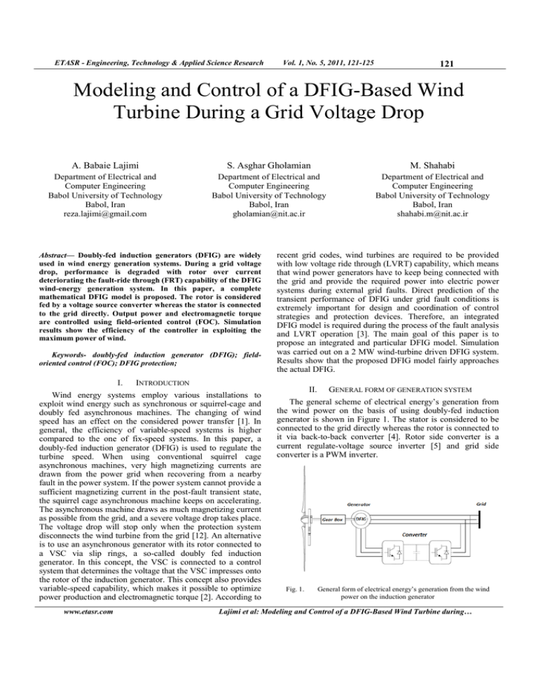
ETASR - Engineering, Technology & Applied Science Research Vol. 1, o. 5, 2011, 121-125 121 Modeling and Control of a DFIG-Based Wind Turbine During a Grid Voltage Drop A. Babaie Lajimi S. Asghar Gholamian M. Shahabi Department of Electrical and Computer Engineering Babol University of Technology Babol, Iran reza.lajimi@gmail.com Department of Electrical and Computer Engineering Babol University of Technology Babol, Iran gholamian@nit.ac.ir Department of Electrical and Computer Engineering Babol University of Technology Babol, Iran shahabi.m@nit.ac.ir Abstract— Doubly-fed induction generators (DFIG) are widely used in wind energy generation systems. During a grid voltage drop, performance is degraded with rotor over current deteriorating the fault-ride through (FRT) capability of the DFIG wind-energy generation system. In this paper, a complete mathematical DFIG model is proposed. The rotor is considered fed by a voltage source converter whereas the stator is connected to the grid directly. Output power and electromagnetic torque are controlled using field-oriented control (FOC). Simulation results show the efficiency of the controller in exploiting the maximum power of wind. Keywords- doubly-fed induction generator (DFIG); fieldoriented control (FOC); DFIG protection; I. INTRODUCTION Wind energy systems employ various installations to exploit wind energy such as synchronous or squirrel-cage and doubly fed asynchronous machines. The changing of wind speed has an effect on the considered power transfer [1]. In general, the efficiency of variable-speed systems is higher compared to the one of fix-speed systems. In this paper, a doubly-fed induction generator (DFIG) is used to regulate the turbine speed. When using conventional squirrel cage asynchronous machines, very high magnetizing currents are drawn from the power grid when recovering from a nearby fault in the power system. If the power system cannot provide a sufficient magnetizing current in the post-fault transient state, the squirrel cage asynchronous machine keeps on accelerating. The asynchronous machine draws as much magnetizing current as possible from the grid, and a severe voltage drop takes place. The voltage drop will stop only when the protection system disconnects the wind turbine from the grid [12]. An alternative is to use an asynchronous generator with its rotor connected to a VSC via slip rings, a so-called doubly fed induction generator. In this concept, the VSC is connected to a control system that determines the voltage that the VSC impresses onto the rotor of the induction generator. This concept also provides variable-speed capability, which makes it possible to optimize power production and electromagnetic torque [2]. According to www.etasr.com recent grid codes, wind turbines are required to be provided with low voltage ride through (LVRT) capability, which means that wind power generators have to keep being connected with the grid and provide the required power into electric power systems during external grid faults. Direct prediction of the transient performance of DFIG under grid fault conditions is extremely important for design and coordination of control strategies and protection devices. Therefore, an integrated DFIG model is required during the process of the fault analysis and LVRT operation [3]. The main goal of this paper is to propose an integrated and particular DFIG model. Simulation was carried out on a 2 MW wind-turbine driven DFIG system. Results show that the proposed DFIG model fairly approaches the actual DFIG. II. GENERAL FORM OF GENERATION SYSTEM The general scheme of electrical energy’s generation from the wind power on the basis of using doubly-fed induction generator is shown in Figure 1. The stator is considered to be connected to the grid directly whereas the rotor is connected to it via back-to-back converter [4]. Rotor side converter is a current regulate-voltage source inverter [5] and grid side converter is a PWM inverter. Fig. 1. General form of electrical energy’s generation from the wind power on the induction generator Lajimi et al: Modeling and Control of a DFIG-Based Wind Turbine during… ETASR - Engineering, Technology & Applied Science Research III. MODEL AND EQUATIONS OF WIND TURBINE Amount of power that wind turbines can extract from wind can be expressed as: 1 2 πρ R 2Vw3 (1) Pm = ωt 2 3 1 ρπ R C p vw ρ is the air density, R is the blades radius of the wind turbine, Vw is the wind speed and C p is the efficiency index [6]. The efficiency index ( C p ) represents the part of the actual wind energy that is extractable by wind turbine and is depended to the blade’s aerodynamic form, as described by: Cp = f (λ, β ) where Ta is the torque in turbine shaft. λ= (2) vw where λ is the ratio of turbine blades tip speed to wind speed, β is the blade angle and IV. MACHINE EQUATIONS The equations of induction machines in the dq reference frame, with the speed of and neglecting zero parameter is given by [8]: Vds = R s i ds − ωψ qs + Vqs = R s i qs + ωψ ds + dψ ds dt dψ qs dt Vdr = Rr idr − (ω − ωr )ψ qr + Rωt ωt is the turbine blades rotational speed. In a wind turbine, C p can be represented by a nonlinear curve in terms of λ in place of different β or the following relationship [7]: (4) ωt 2 Where Pm is the mechanical power that is extracted from the wind by the wind turbine, Pw is the actual wind power, 122 In wind turbine simulation, generation torque is modeled in variable-speed of turbine as is represented below: Ta = Pm = C p Pw Pw = Vol. 1, o. 5, 2011, 121-125 Vqr = Rr iqr − (ω − ωr )ψ dr + dψ dr dt dψ qr (5) dt Where Vds and Vqs are the d- and q-axis stator voltages, Vdr and Vqr are the d- and q-axis rotor voltages, i ds and i qs are the d-and q-axis stator currents, and i dr and i qr are the d– and q-axis rotor currents. R s and R r are the per-phase stator and rotor resistances referred to the stator, ψ ds and ψ qs are the d- and q-axis stator flux linkages ,and ψ dr and ψ qr are the d– π ( λ − 2) C p = ( 0.44 − 0.0167 β ) sin 13 − 0.3β −0.00184 ( λ − 2 ) β (3) and q-axis rotor flux linkages. ω is the speed of rotation of the dq frame, and ωr is the rotor electrical angular velocity. The rotor electrical angular velocity is related to the rotational speed 2 of the machine through the relationship ωm = ( )ωr , where p p is the number of machine poles. The developed electromagnetic torque Tem is given by: Tem = 3P 4 (i ψ qs ds − idsψ qs ) (6) The equation relating the speed of rotation of the machine to the electromagnetic and applied mechanical torque is given by: J Fig. 2. nonlinear curve in terms of www.etasr.com λ in place of different β d ωm dt = Tmech + Tem (7) Where in this relationship J is the polar moment of inertia of the machine and prime mover referred to the inductionmachine shaft. Lajimi et al: Modeling and Control of a DFIG-Based Wind Turbine during… ETASR - Engineering, Technology & Applied Science Research FIELD-ORIENTED CONTROL (FOC) V. The induction-machine model presented in this section may also be used to simulate the operation of a doubly fed induction machine. In addition to the machine model, a model of the power converter and its associated controls must also be included. The controller of a DFIG is typically configured to allow the adjustment of the rotation speed of the WTG. However, employing an appropriate choice of reference frame, the task can be simplified, upon which control of the field-oriented quantities allows for independent control of the electromagnetic torque. This technique is known as FOC. The controlled back-to-back converter of a DFIG is typically connected through slip rings to the rotor windings, and independent torque control is usually achieved through control of the rotor current [9]. The model of the FOC can be developed for the DFIG by rewriting equation (1) as: Rs R s Lm ψ ds − ωψ qs − Ls Ls Rs RL Vds = p + Vqs = ωψ ds + p + Vdr = Lm Ls i dr (8) s m i qr ψ qs − Ls Ls (9) pψ ds − ( ω − ωr ) Lm Ls pψ qs (10) mutual inductance per-phase and Lα = Lm − Lr Ls . The expression for electromagnetic torque (6) can also be rewritten in terms of rotor current as: 2 qr ψ ds + i dr ψ qs ) (12) Examining (12), it can be seen that in order to have control over the electromagnetic torque, it is desirable to have ψ ds = 0 . The torque equation reduces to: Tem = 3P Lm 4 Ls idrψ qs (13) Allowing the electromagnetic torque to be controlled by adjusting idr . The speed of the rotation of the reference frame can be calculated as: www.etasr.com (14) ψ qs A mean of controlling can be established by examining (10) and (11) with the condition that ψ ds = 0 . Vdr = − ( ω − ωr ) + ( ω − ωr ) Vqr = Lm Ls Lα Ls + Rr − Lm Ls Lα Ls pψ qs + Rr − p idr Lα iqr Ls (15) pψ qs − (ω − ωr ) Lα idr Ls (16) p iqr Many FOC DFIG models, use an induction-machine model as described in this section coupled with a model of the FOC, and ultimately, yielding the final dynamic equation in the equivalent FOC DFIG model [9]: Rs RL s m i qr ψ qs − Ls Ls Gd ( S ) = idr Gq ( S ) = iqr (11) inductance per-phase referred to the stator, and Lm is the ( −i Vds i dr − ψ qs Ls 123 (17) If the closed-loop response of the current control loops are represented by the transfer functions: Where Ls is the per-phase stator inductance, Lr is the rotor 4 Ls Rs L m L L − (ω − ωr ) α idr + Rr − α p iqr Ls Ls Tem = ω=− Vqs = p + L L + Rr − α p idr + ( ω − ωr ) α iqr Ls Ls L L Vqr = (ω − ωr ) m pψ ds + m pψ qs Ls Ls 3P Lm Vol. 1, o. 5, 2011, 121-125 (18) idr* (19) iqr* * * Where idr and iqr are the reference d- and q-axis rotor * currents and The reference signal idr is derived from a required * electromagnetic torque set point Tem according to (13), with iqr* derived from a stator reactive power set point. First-order current-controller response was assumed for the FOC DFIG model as below [10, 11]: Gd ( S ) = 1 (1 + sτ d ) Gq ( S ) = 1 (1 + sτ ) (20) (21) q Where τ d and τ q are the d- and q-axis times constant of current-controller. Lajimi et al: Modeling and Control of a DFIG-Based Wind Turbine during… ETASR - Engineering, Technology & Applied Science Research VI. Vol. 1, o. 5, 2011, 121-125 124 SIMULATIONS RESULTS In this part, the effect of voltage drop has been evaluated using the presented model. The applied voltage drop is about 20 percent and its effect on the rotor rotational speed ωm , the electromagnetic torque Tem , and electrical power is examined. It was assumed that the WTG was connected to an infinite bus bar, and thus, the system frequency at the point of connection of the wind turbine remains constant during the event. The FOC and DFIG models were simulated in MATLAB/Simulink using the parameters from a 2-MW WTGbased induction machine, listed in Table I. It was also assumed that the WTG is largely insensitive to small variations in rotational speed, and thus, Tmech was held constant during the voltage drop. During normal operation of a WTG, the signal Fig. 3. Current-controller response * Tem is supplied from an external control loop, which adjusts the speed of the WTG. This way maximum energy is extracted at below rated wind speeds, and power smoothing is achieved at and above rated wind speed. As the wind speed was assumed * constant during the voltage drop, the reference torque Tem remained constant during the event. The resulting closed-loop current-controller response for the voltage drop, is shown in Figure 3. Figure 4 shows the effect of the measured system’s voltage drop on the rotational speed of FOC DFIG-based WTG model. TABLE I. Fig. 4. FOC DFIG rotational speed in response to grid voltage drop 2-MW WTG INDUCTION MACHINE PARAMETERS Parameter Value Ω Rs 1 .7 4 8 × 1 0 − 2 Rr 3 .2 5 3 × 1 0 −2 Ω 2 .5 8 9 × 1 0 −2 H 2 .6 0 4 × 1 0 −2 H 2 .4 9 2 × 1 0 −2 H Ls Lr Lm P J ρ 6 1 .3 9 × 1 0 2 k g .m 1.25 k g m 2 R 33 m Vw 8 m s 690 v 2MW Vs Rated power 2 Fig. 5. FOC DFIG electromagnetic torque in response to grid voltage drop The effect of the reduction in system voltage on the electromagnetic torque can be seen in Figure 5. The inertial response that results from the decrease in rotational speed and release of kinetic energy can be seen by observing the generated electrical power, as shown in Figure 6, where an increase in generated electrical power can be observed immediately following the voltage drop. Fig. 6. www.etasr.com FOC DFIG-generated electrical power in response to grid voltage drop Lajimi et al: Modeling and Control of a DFIG-Based Wind Turbine during… ETASR - Engineering, Technology & Applied Science Research This paper investigated the transient performances of DFIG during grid voltage dips. On the basis of an ideal model, an integrated DFIG model is proposed. From the simulation results, it is shown that the DFIG model approaches the behavior of the actual DFIG. The presented results can be used in order to fully evaluate the fault degrees when designing protection schemes and also for future research on improved control strategies and the fault ride through capability for DFIG-based wind power generation systems. REFERENCES [2] [3] [4] [5] [6] A. Mullane, G. Lightbody, R. Yacamini, “Adaptive control of variable speed wind turbines”, n proceedings of 36th Universities Power Engineering Conference, Swansea, 2001 T. Ackermann, Wind Power in Power Systems, John Wiley & Sons, 2005 J. Zhao, W. Zhang, Yikang He, J.HuI, “Modeling and control of a windturbine-driven DFIG incorporating core saturation during grid voltage dips” International Conference on Electrical Machines and Systems (ICEMS 2008), pp. 2438 – 2442, 2008 W. Hofmann, "Optimal reactive power splitting in wind power plants controlled by double-fed induction generator" IEEE AFRICON, pp 943948, South Africa, 1999 A. Petersson, "Analysis, modeling and control of doubly-fed induction generators for wind turbines", Technical report no. 464L, School of Electrical Engineering, Chalmers University of Technology, Goteborg, Sweden, 2003 Chee-Mun Ong, Dynamic simulation of electric machinary using Matlab/Simulink, Prentice Hall, 1998 www.etasr.com 125 [7] VII. CONCLUSION [1] Vol. 1, o. 5, 2011, 121-125 P. Kundur, N. J. Balu, M. G. Lauby, Power system stability and control, McGraw-Hill, 1994 [8] P. Kundur, Power system stability and control, McGraw-Hill, 1994 [9] N. Hur, J. Jung, K. Nam, “A fast dynamic DC-link power-balancing , scheme for a PWM converter-inverter system”, IEEE Transactions on Industrial Electronics., Vol. 48, No. 4, pp. 794–803, 2001 [10] A. Mullane, M. O’Malley, “The Inertial Response of InductionMachine-Based Wind Turbines,” IEEE Transactions on Power Systems, Vol. 20, No.3, pp. 1496 - 15033, 2005 [11] M. Cichowlas, M. Kamierkowski, “Comparison of current control techniques for PWM rectifiers”, IEEE International Symposium on Industrial Electronics, Vol. 4, pp. 1259–1263, 2002 [12] V. Akhmatov, “Variable-speed wind turbines with doubly-fed induction generators, part I: modelling in dynamic simulation tools”, Wind Engineering, Vol. 26, No. 2, pp. 85–108, 2002 Lajimi et al: Modeling and Control of a DFIG-Based Wind Turbine during…


